Supporting assembly and method for using the same

Active Publication Date: 2015-06-25
UNITED MICROELECTRONICS CORP
View PDF16 Cites 4 Cited by
  • Summary
  • Abstract
  • Description
  • Claims
  • Application Information

AI Technical Summary

Benefits of technology

[0009]One main characteristic of the embodiment is that the tubes are able to be received by the parallel recesses and therefore to be supported by the supporting assembly. In this way, friction

Problems solved by technology

The flexible tubes, however, often need to be replaced since they inevitably wear out dur

Method used


Image

  • Supporting assembly and method for using the same
  • Supporting assembly and method for using the same
  • Supporting assembly and method for using the same

Examples


Embodiment Construction

[0017]In the following description, numerous specific details are given to provide a thorough understanding of the invention. It will, however, be apparent to one skilled in the art that the invention may be practiced without these specific details. Furthermore, some well-known system configurations and process steps are not disclosed in detail, as these should be well-known to those skilled in the art.

[0018]Likewise, the drawings showing embodiments of the apparatus are not to scale and some dimensions are exaggerated for clarity of presentation. Also, where multiple embodiments are disclosed and described as having some features in common, like or similar features will usually be described with same reference numerals for ease of illustration and description thereof.

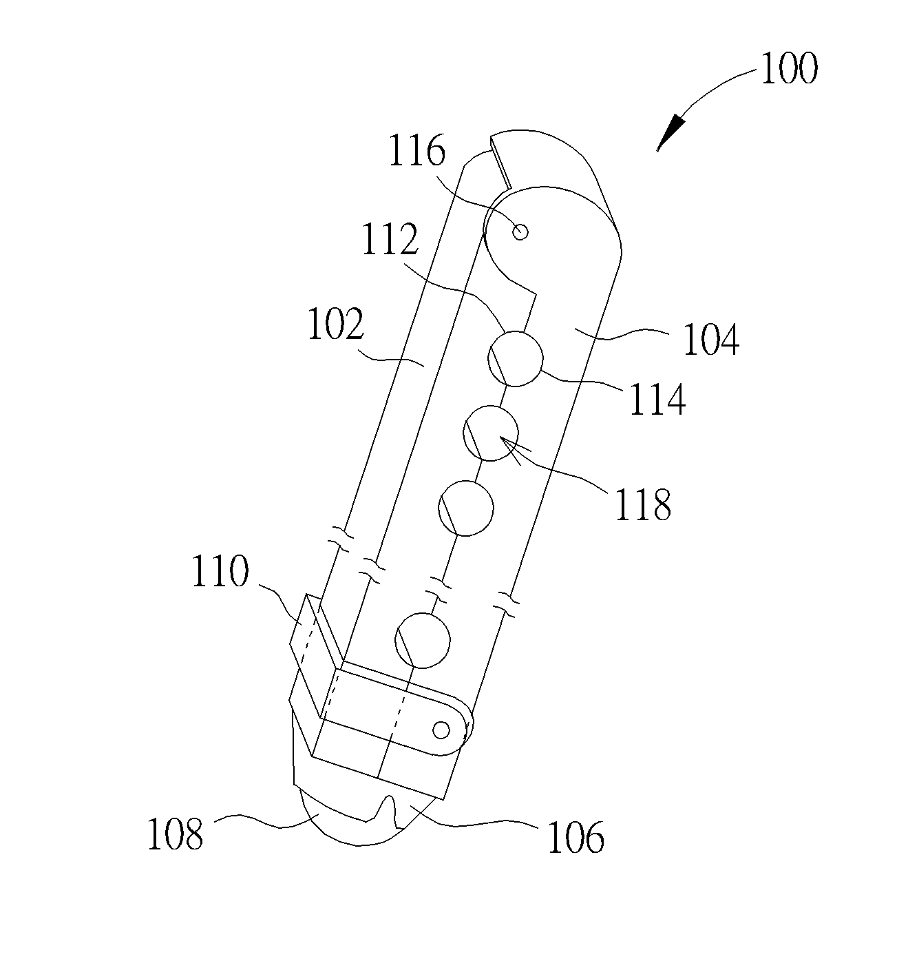
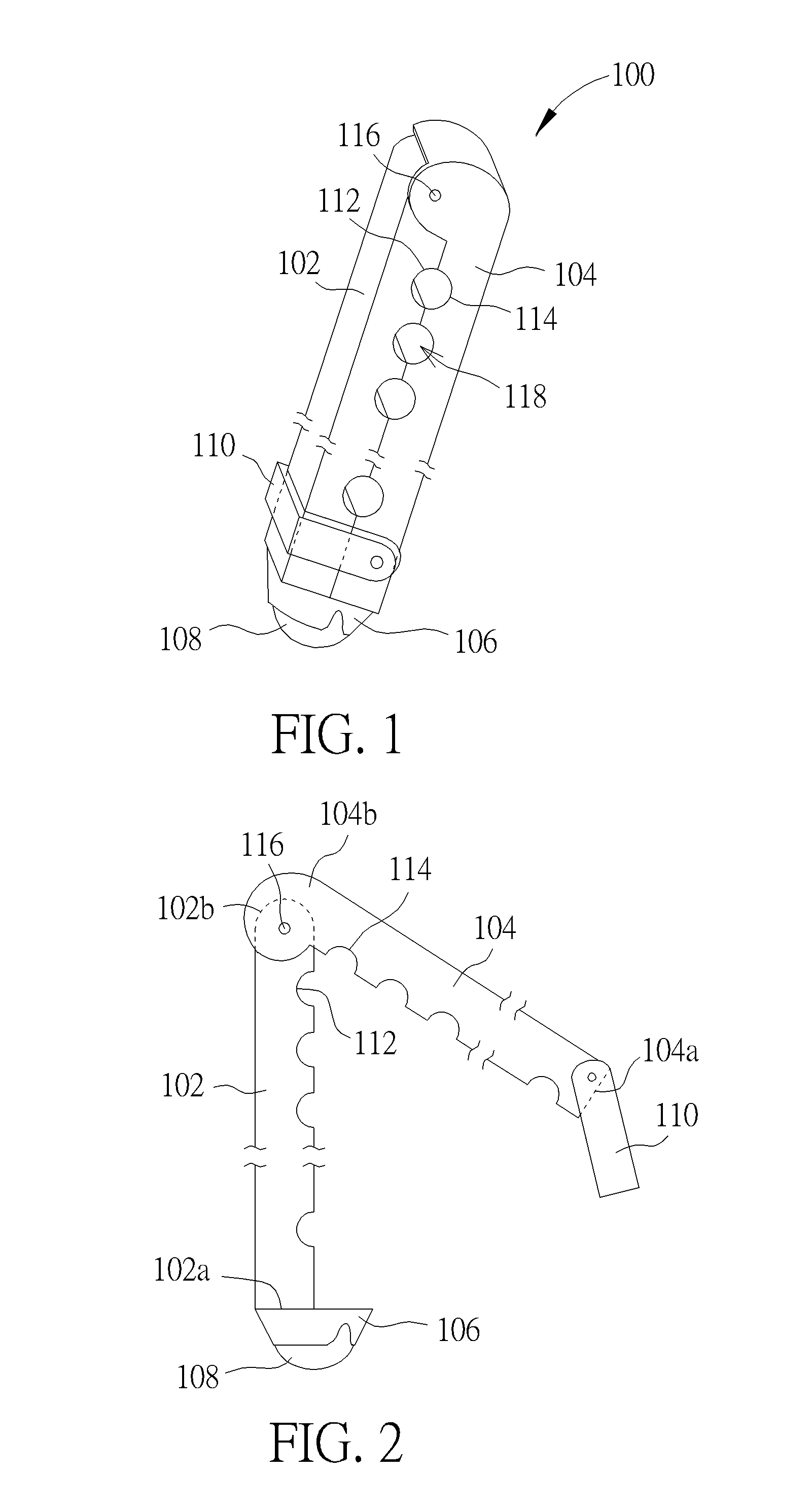
[0019]Please refer to FIG. 1 and FIG. 2. FIG. 1 is a schematic perspective diagram showing a supporting assembly according to a first embodiment of the present invention. FIG. 2 is schematic side view of FIG. 1 showing...


PUM


Abstract

A supporting assembly configured to support a plurality of tubes includes a first supporting rod, a second supporting rod opposite to the first supporting rod, a bridging member, and a rolling member. The first supporting rod includes several first parallel recesses. The bridging member is connected to one end of the first supporting rod or one end of the second supporting rod. The rolling member is received by the bridging member.

Description

BACKGROUND OF THE INVENTION[0001]1. Field of the Invention[0002]The present invention generally relates to the field of a supporting apparatus, and more particularly to a supporting assembly configured to support flexible tubes.[0003]2. Description of the Prior Art[0004]With the increasing miniaturization of semiconductor devices, a variety of projection exposure apparatuses used to transfer patterns from a reticle to a substrate have been invented. Currently, in order to improve both the resolutions and the depth of the focus (DOF), immersion exposure apparatuses have been developed and are widely adopted by the semiconductor manufactures.[0005]Briefly, the basic working principle of the immersion exposure apparatus is that the space between an objective lens and a photosensitive layer can be filled with high-index liquid during an exposure process. By the use of high-index liquid, the light passing through the objective lens may be further concentrated before it reaches the surfac...

Claims


Application Information

Patent Timeline
IPC IPC(8): F16L3/10G03F7/20H01L21/308
CPCF16L3/1033G03F7/2041H01L21/3086F16L3/01F16L3/2235G03F7/70825G03F7/70341F16L3/10G03F7/709G03F7/70816H01L21/0335H01L21/0337H01L21/0338
Inventor WU, CHIEN-JUWU, MING-SUNG
Owner UNITED MICROELECTRONICS CORP
Why Eureka
Try Eureka