Liquid Ring Compressor

a compressor and ring technology, applied in the direction of liquid fuel engines, pumps, mechanical equipment, etc., can solve the problems of compressor instability, detracting from the overall efficiency of the compressor, and inertial instability

Active Publication Date: 2009-11-26
AGAM ENERGY SYST
View PDF11 Cites 16 Cited by
  • Summary
  • Abstract
  • Description
  • Claims
  • Application Information

AI Technical Summary

Benefits of technology

[0005]It is therefore a broad object of the present invention to overcome the above-described disadvantages and to provid...

Problems solved by technology

This known LRC, however, has several disadvantages: while the jacket is free to rotate by the liquid ring which is driven by the rotor, the velocity of the rotating casing lags behind the rotor's tips, rendering the flow unstable namely, causing inertial instability, especially when the angular momentum becomes smaller with large radiuses (the angular momentum of a liquid element located at a radius r is defined as the produces u·r, where u is the tangent...

Method used


Image

  • Liquid Ring Compressor
  • Liquid Ring Compressor
  • Liquid Ring Compressor

Examples


Embodiment Construction

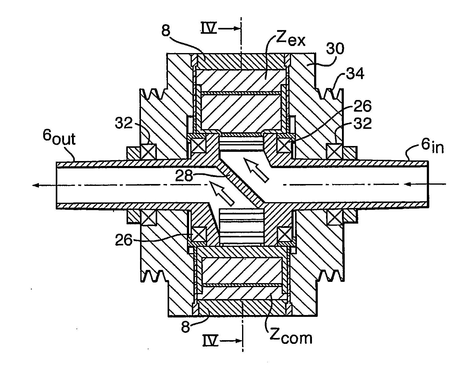
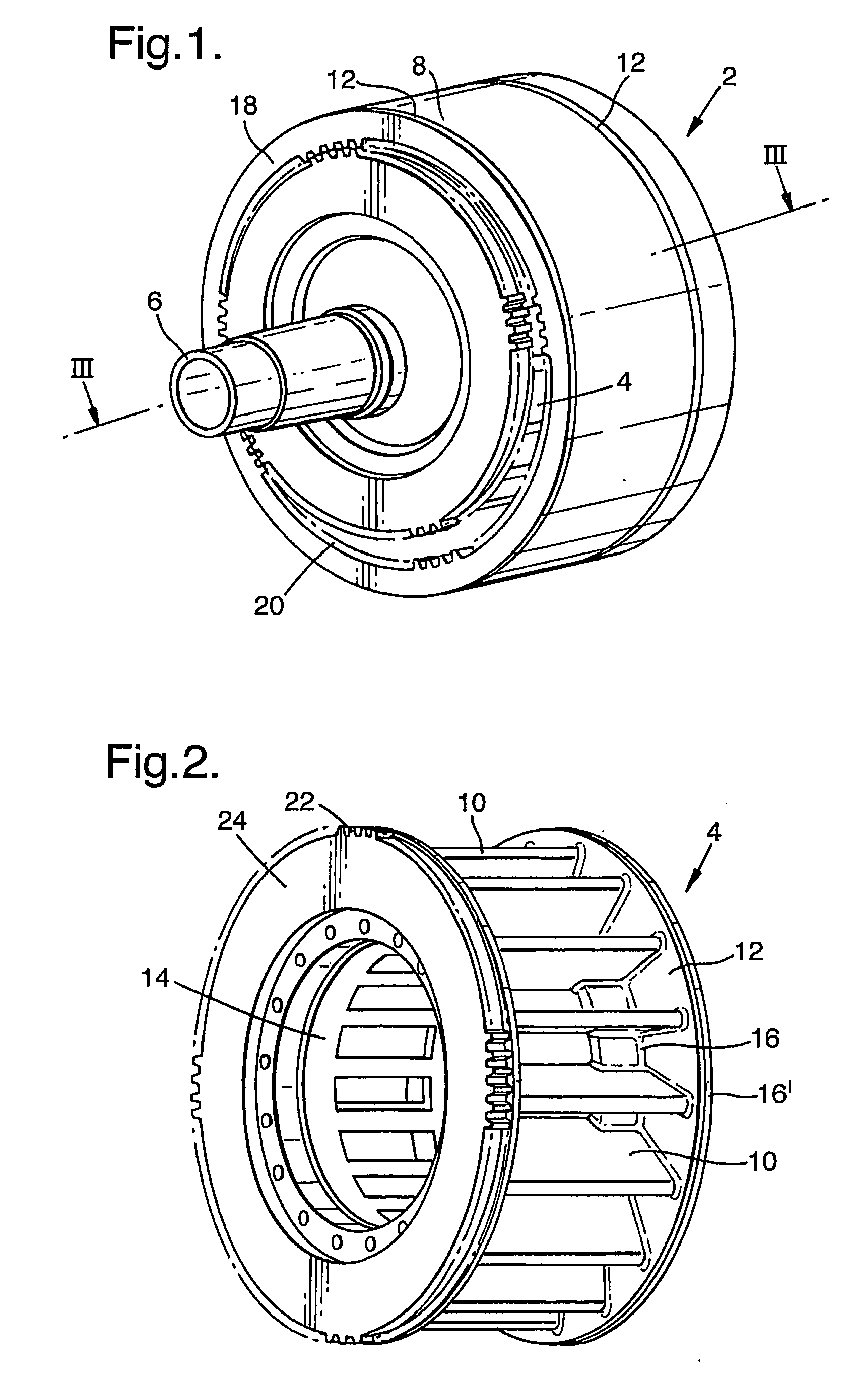
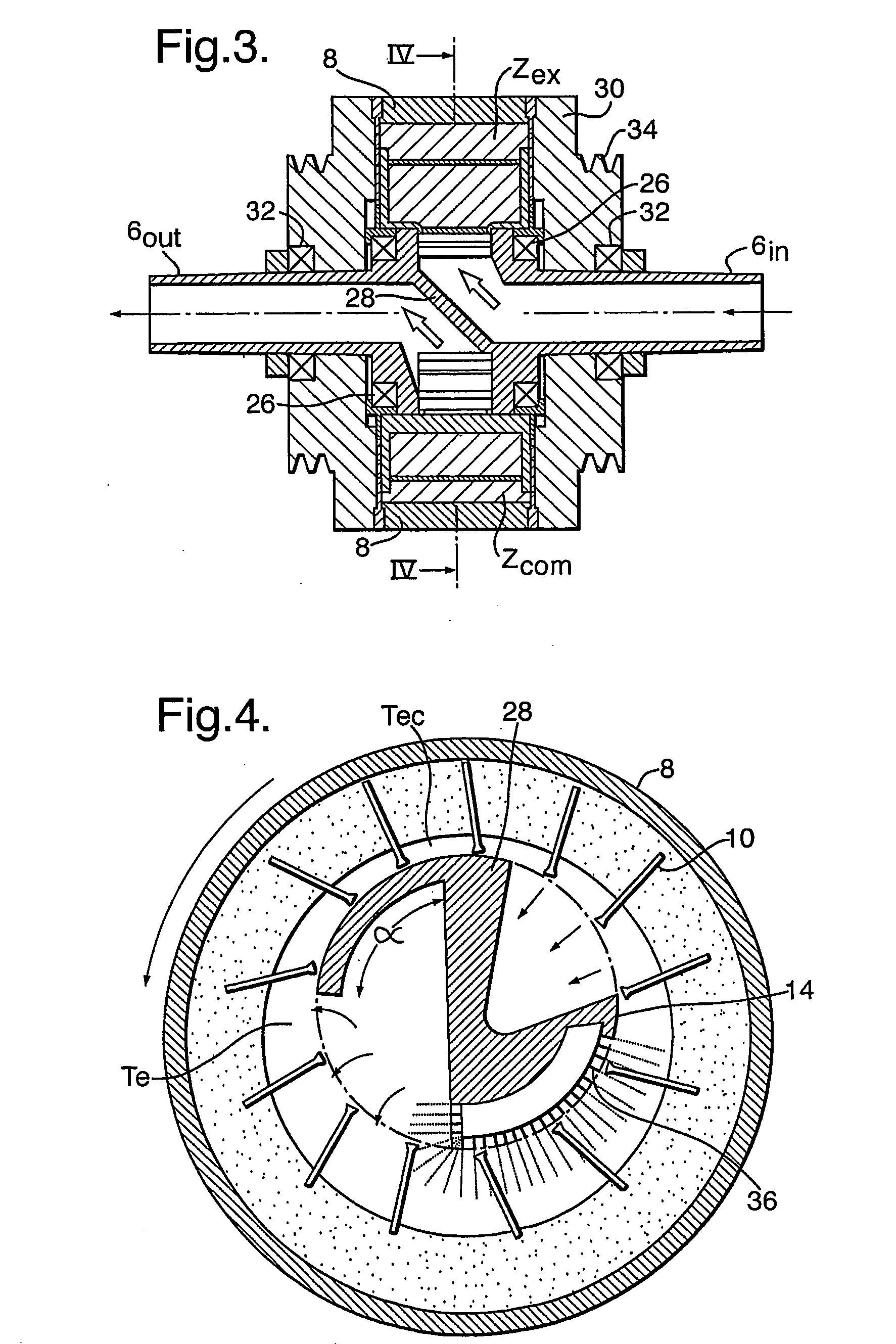
[0017]An isometric, partly exposed view of the LRRCC 2 according to the present invention is shown in FIG. 1. The compressor 2 having a general cylindrical shape, is composed of three major parts: an inner impeller 4 mounted on a shaft 6 and a casing 8, configured as a curved surface of a cylinder. The shaft 6 is stationary and advantageously hollow, and the impeller 4 is rotatably coupled thereon, as seen in detail in FIG. 3. The impeller 4 shown in FIG. 2 consists of a plurality of radially extending vanes 10 mounted about a core 14, and of ring-shaped side walls 12, having concentric inner edges 16 and outer edges 16′. Advantageously, as seen in the Figure, the vanes 10 terminate shorter than the outer edges 16 for reasons that will be discussed hereinafter. Further seen in FIG. 1 is the casing 8 eccentrically rotatably coupled with the impeller 4 and extending across the outer edges of the vanes 10 between the side walls 12. Optionally, the casing 8 is mechanically coupled to th...


PUM


Abstract

A liquid ring rotating casing compressor (LRRCC), including a shaft, an impeller having a core and a plurality of radially extending vanes rotatably coupled to the shaft, a tubular casing having an inner surface and an outer surface eccentrically rotatably disposed with the impeller and disc-shaped portions laterally coupled to the vanes and/or to the core. The casing defines with the impeller a compression zone, wherein edges of the vanes rotate in increasing proximity to an inner surface of the casing and an expansion zone and edges of the vanes rotate in increasing spaced-apart relationship along an inner surface of the casing. An inlet port communicates with the expansion zone, an outlet port communicates with the compression zone, and there is also provided a drive for rotating motion to the casing.

Description

FIELD OF THE INVENTION[0001]The present invention relates to Liquid Ring Compressors (LRC's) and more specifically to an LRC with a rotating casing.BACKGROUND OF THE INVENTION[0002]U.S. Pat. No. 5,636,523 discloses an LRC and expander having a rotating jacket, the teaching of which is incorporated herein by reference.[0003]This known LRC, however, has several disadvantages: while the jacket is free to rotate by the liquid ring which is driven by the rotor, the velocity of the rotating casing lags behind the rotor's tips, rendering the flow unstable namely, causing inertial instability, especially when the angular momentum becomes smaller with large radiuses (the angular momentum of a liquid element located at a radius r is defined as the produces u·r, where u is the tangential velocity). As the liquid velocity near the jacket follows the jacket's velocity, when the jacket's velocity lags behind the rotor's velocity, the friction, which is formed between the liquid and the jacket and...

Claims


Application Information

Patent Timeline
IPC IPC(8): F04C19/00
CPCF01C17/02F04C29/042F04C19/002F01C21/0809F04C7/00F04C19/004F04C19/008
Inventor ASSAF, GAD
Owner AGAM ENERGY SYST
Why Eureka
Try Eureka