
System and method for an adjustable connector

a technology of adjustable connectors and connectors, which is applied in the direction of curtain suspension devices, door/window protective devices, shutters/movable grilles, etc., can solve the problems of uneven shading of the fabric, and the inability to adjust the shadebands, so as to minimize the differences between adjacent shadebands and minimize friction

Active Publication Date: 2007-11-01
MECHOSHADE SYST LLC
View PDF4 Cites 27 Cited by
  • Summary
  • Abstract
  • Description
  • Claims
  • Application Information

AI Technical Summary

Benefits of technology

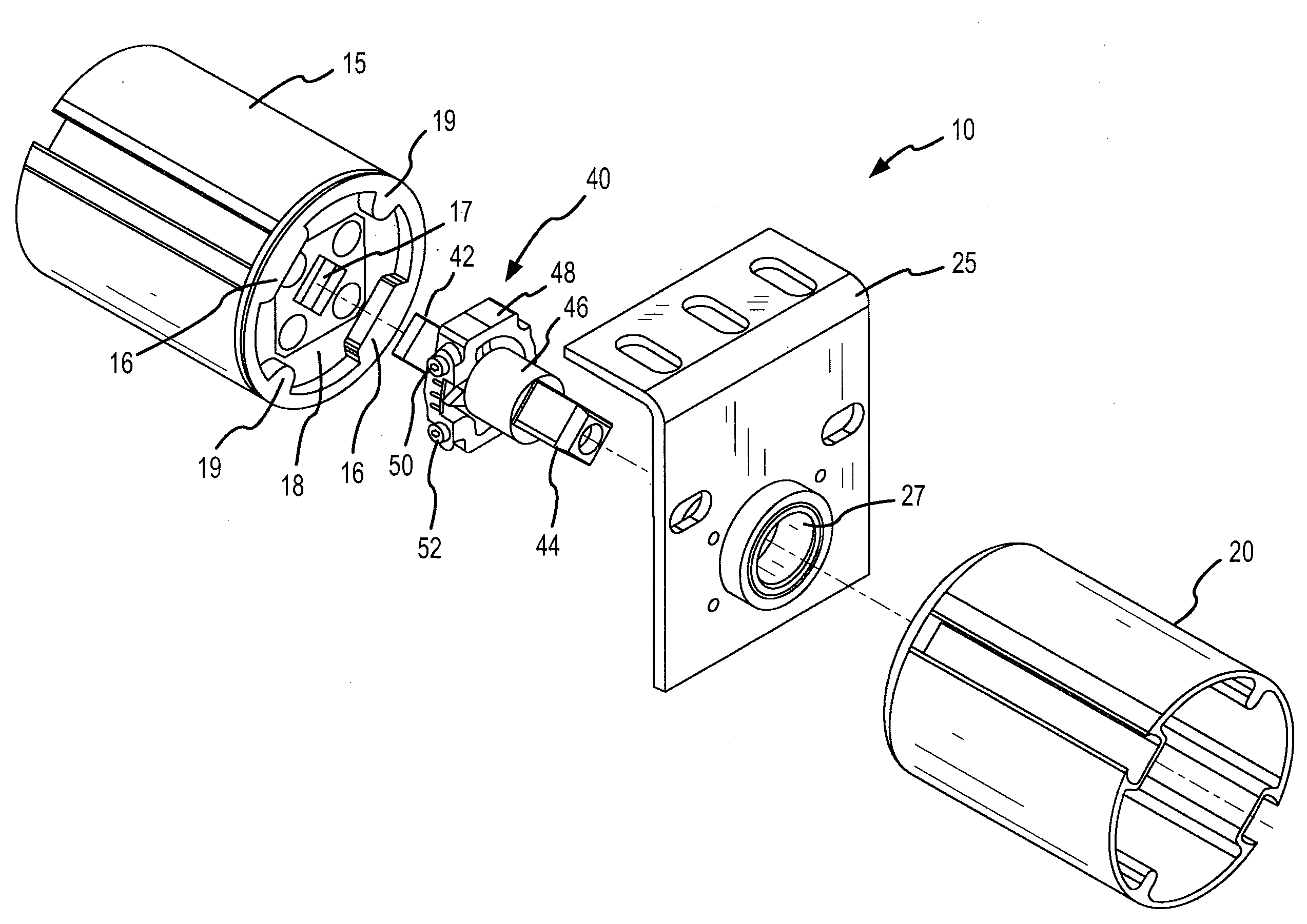
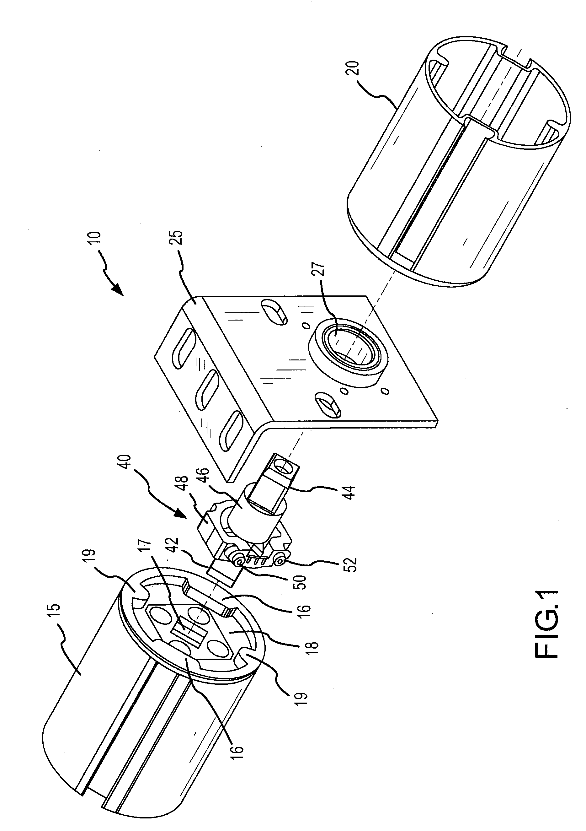
The coupler system described in this patent allows for the adjustment of the relationship between adjacent shade tubes in a shading system. This is achieved by using an adjustable shade tube connector that can be rotated to compensate for the height of the shade at the bottom of the shade. The adjustment is made without affecting the shape of the rollertube, minimizing differences between adjacent shadebands. The coupler system includes a head component, drive shafts, and an adjustment device that rotates the cam to align the hem bars on the tubes. The system is easy to install and maintains uniformity of edge clearance between the center support bracket and the adjustable coupler.

Problems solved by technology

The deflection of the roller tube can negatively affect the flatness of the fabric falling on a shade which causes, under negative circumstances, a partial or full “smile” ripple across the fabric.
Furthermore, multi-banded shade assemblies are often very difficult to install.
However, without an adjustment facility in the coupling mechanism, various factors may cause the shadebands to misalign.
Common industry practices such as, for example, “shimming” of the shadeband are usually very time consuming and only align the shade at one point in the shade's positioning.
Thus, if a user tries to stop the shade assembly somewhere in the middle of the window after shimming it at the bottom, the bands are typically no longer aligned.
Over multiple rotations, the effect of any differences in tube shape, and ultimately the correlation of rotational angle with circumference, affect fabric take-up on the roller tube, thereby magnifying the misalignment and causing larger and larger misalignment between the adjacent bands.

Method used


Image

  • System and method for an adjustable connector
  • System and method for an adjustable connector
  • System and method for an adjustable connector

Examples


Embodiment Construction

[0014]The detailed description of exemplary embodiments describes the exemplary embodiment by way of illustration and its best mode. While these exemplary embodiments are described in sufficient detail to enable those skilled in the art to practice the invention, it should be understood that other embodiments may be realized and that logical and mechanical changes may be made without departing from the spirit and scope of the invention. Thus, the detailed description herein is presented for purposes of illustration only and not of limitation. For example, the steps recited in any of the method or process descriptions may be executed in any order and are not limited to the order presented. Moreover, any of the functions or steps may be outsourced to or performed by one or more third parties. Furthermore, any reference to singular includes plural embodiments, and any reference to more than one component may include a singular embodiment.

[0015]In general, the present invention includes...


PUM


Abstract

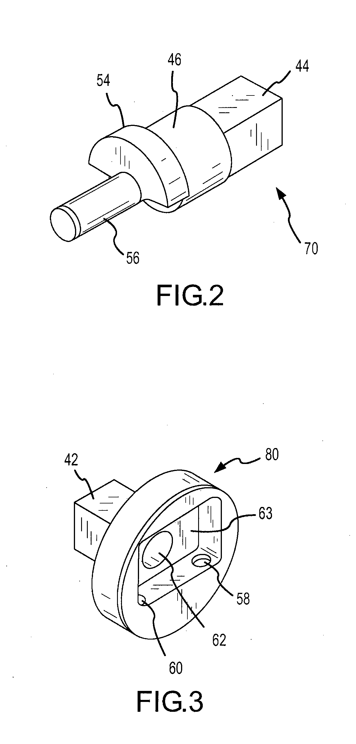
A coupler system which changes the relationship of two or more rotating shade tubes is disclosed. The invention enables the installer to compensate for the height of the hembar by rotating the tube forward or backward any desired number of degrees. The coupler includes a cam which is adjusted by opposing set screws. The cam may be rotated by about 15 degrees in each direction. Adjusting the cam adjusts the second tube without adjusting the first tube (e.g., the drive or motor end tube). The adjustment device is configured to rotate the cam which, in turn, rotates the second tube to align a second hem bar hanging from the second tube with a first hem bar hanging from the first tube. The adjustments may be accomplished with minimal or no removal or adjustment of the other shades, and with minimal friction on the aligned shade.

Description

CROSS-REFERENCE TO RELATED APPLICATIONS[0001]This application claims priority to, and the benefit of, U.S. Provisional Application Ser. No. 60 / 745,699, filed Apr. 26, 2006, which is hereby incorporated by reference in its entirety.FIELD OF INVENTION[0002]The present invention generally includes a coupling device, and more particularly, a coupling device utilized in “multi-banded” shade assemblies.BACKGROUND OF THE INVENTION[0003]A multi-banded shade assembly includes a shade assembly comprising multiple smaller width shadebands. Multi-banded shade assemblies may occur in manual (e.g., chain / rope clutch assembly) and / or motorized shading systems. Multi-banded shade assemblies are advantageous because they can employ a single (or reduced) drive mechanism to operate multiple bands, thereby reducing cost and increasing maintenance efficiency. Multi-banded shade assemblies are also advantageous because they can drive a larger shade width (often times better as an assembly than as a singl...

Claims


Application Information

Patent Timeline
Patent Type & Authority Applications(United States)
IPC IPC(8): E04C5/16
CPCE06B9/174E06B9/40E06B2009/1746F16D1/12Y10T403/76Y10T403/32409Y10T403/5733Y10T403/1624Y10T403/7041
Inventor LI, XI MINGHEBEISEN, STEVEVASAPOLLI, SALVATORE
Owner MECHOSHADE SYST LLC
Learn More