Evaluation of fracture geometries in rock formations

a fracture geometrie and rock formation technology, applied in the field of hydraulic fracture geometries evaluation, can solve the problems of general information, lack of quantitative information on the main fracture, and inability to provide exact fracture geometry information

Inactive Publication Date: 2005-01-27
SCHLUMBERGER TECH CORP
View PDF9 Cites 76 Cited by
  • Summary
  • Abstract
  • Description
  • Claims
  • Application Information

AI Technical Summary

Benefits of technology

It is an object of the present invention to provide a method for evaluating fracture geometries in rock formations surr...

Problems solved by technology

This approach provides, however, only very general information about fracture length and fracture width and does not provide any information about the exact fracture geometry.
However, they do not provide direct quantitative information on the main fracture.
The approach is commonly used in the field and is particularly suited for the estimation of fracture azimuth and dip, but not for an accurate determination of the position of the fracture tip.
Another disadvantage of the approach...

Method used


Image

  • Evaluation of fracture geometries in rock formations
  • Evaluation of fracture geometries in rock formations
  • Evaluation of fracture geometries in rock formations

Examples


Embodiment Construction

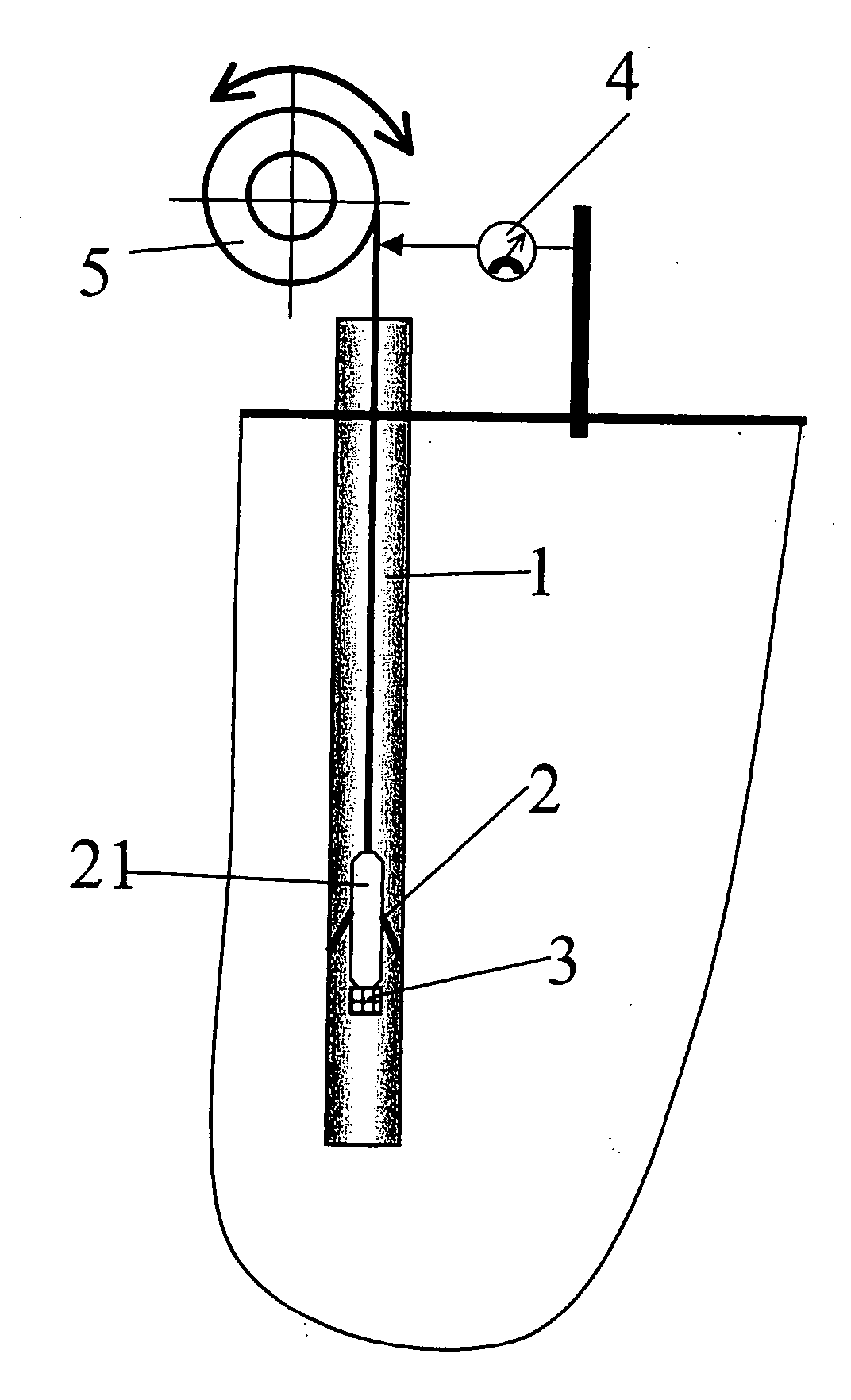
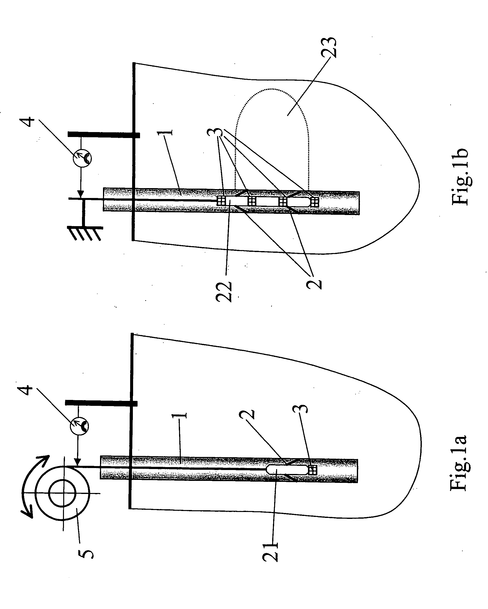
FIG. 1a is a schematic view of a borehole 1 with a sensor arrangement (associated with a downhole tool) 21 which comprises electric field sensors 2 and magnetic field sensors 3. The electric field sensors 2 are voltage electrodes which contact the borehole and the magnetic field sensor 3 is a magnetometer, such as a high-precision nuclear magnetic resonance device of the type provided, for example, by Schlumberger. Examples of suitable electrodes and magnetometers are described in: U.S. Pat. No. 5,642,051 and U.S. Pat. No. 6,441,618 for electrodes behind casing; EP0544583 and EP0715187 for electrodes on a wireline tool in openhole; and U.S. Pat. No. 6,597,178B1 and Etchecopar et al. (1993), Harnessing Paleomagnetics for Logging, Oilfield Review, October 1993, Volume 5, Number 3 for magnetometers. The sensor arrangement 21 is movable along the borehole by means of a drive 5, thus providing measurement of electric and magnetic fields in different parts of the borehole. In this example...


PUM


Abstract

A method of evaluating the geometry of a hydraulic fracture in a rock formation comprises the steps of: obtaining measured values of electric and/or magnetic fields induced by the forward or back propagation of a fracturing fluid between the fracture and the rock formation; and determining the geometry of the fracture from the measured values.

Description

FIELD OF THE INVENTION The present invention relates to a method for evaluating the shape or geometry of hydraulic fractures in rock formations. It can be advantageously applied to determine the shapes of fractures surrounding oil well boreholes. BACKGROUND OF THE INVENTION Hydraulic fracturing is generally used to stimulate production of hydrocarbons from hydrocarbon wells. Hydraulic fractures are created in subterranean formations by injecting high viscosity fluid (also referred to as fracturing fluid) at a high flow rate into well boreholes. The tensile fractures thus-created can be about 100 m long. The fracturing procedure generally takes from about 30 minutes to 4 hours. In order to create a high conductivity drain in the formation, the fracturing fluid usually contains proppants, small particles which are added to the fluid to keep the fracture open once the injection is stopped and pressure is released. These particles can be sand grain or ceramic grains. The width of the...

Claims


Application Information

Patent Timeline
IPC IPC(8): E21B43/26E21B47/00G01V3/26
CPCG01V3/26E21B43/26E21B49/008
Inventor ENTOV, VLADIMIR MORDUKHOVICHGORDEEV, YURY NIKOLAEVICHEVGENY MIKHAILOVICH, CHEKHONINTHIERCELIN, MARC JEAN
Owner SCHLUMBERGER TECH CORP
Why Eureka
Try Eureka