Catheter having a low-friction guidewire lumen and method of manufacture

a low-friction, guidewire technology, applied in the field of medical devices, can solve the problems of increasing the difficulty of balloon accessing the stenosis site, affecting the proper placement of the catheter, and the tendency of the catheter to collapse or buckle axially, so as to improve the trackability over the guidewire

Inactive Publication Date: 2005-08-02
MEDTRONIC VASCULAR INC
View PDF12 Cites 26 Cited by
  • Summary
  • Abstract
  • Description
  • Claims
  • Application Information

AI Technical Summary

Benefits of technology

[0025]It is among the general objects of the present invention to provide an alternative catheter which allows for simple catheter and guidewire exchanges. Specifically, the present invention is a multi-lumen catheter including both a full-length inflation lumen and guidewire lumen that is responsive to applied torque loads, without “flipping,”“bunching” or having various shafts “flex” against one another. Further, the present invention has improved trackability over a guidewire due to minimal friction between the guidewire and guidewire lumen.
[0028]Each node includes a region comprising a crown, that is an innermost portion of the node, which tangentially intersects with and thereby forms the guidewire track. In one embodiment, the crown is formed of a material different than the material used to form the remaining body portion of the catheter. Accordingly, the catheter is formed of at least two materials. The material used to form the body portion of the catheter provides the requisite burst and tensile strength needed to withstand the inflation pressures and torque that the catheter is subjected to during an angioplasty procedure. Whereas the material forming the crown, in addition to have sufficient burst and tensile strength, is a material having a lower coefficient of friction than the material forming the rest of the body of the catheter. This enables smooth and easy travel over a guidewire within the guidewire lumen. Because of the arc-shape, the crown of each node contacts the guidewire at only a single point in cross-section thereby effectively creating “rolling friction” rather than “sliding friction” between the guidewire and the catheter shaft.
[0030]In another embodiment of the balloon catheter of the present invention, the catheter shaft includes nodes that each have an inflation lumen formed therein, which are in fluid communication with a dilatation balloon attached thereto. An outer wall of each inflation lumen creates a convex portion on an exterior surface of the catheter shaft. Each convex portion is separated by an arc-shaped indentation, thereby reducing the total surface area of the catheter shaft in contact with a body lumen when such catheter is tracked therethrough. The guidewire lumen of this embodiment is similar to that described above except that the guidewire lumen arms are shallower, thereby increasing the catheter wall thickness.
[0032]In order to provide additional flexibility at the distal section of the balloon catheter, another embodiment of the present invention includes the catheter design described above only on a proximal section of the balloon catheter. The distal section comprises a coaxial catheter design. A reduction in the number of lumens at the distal portion of the balloon catheter provides additional flexibility where the catheter traverses the particularly tortuous body lumens.
[0033]In this embodiment, a generally circular distal guidewire lumen is disposed coaxially inside a generally circular distal catheter shaft. A distance between the distal guidewire lumen and the distal catheter shaft defines a distal inflation lumen. The distal section is bonded to the proximal section such that the proximal inflation lumen disposed in the nodes of the previous design are fluidly connected to the distal inflation lumen and that the distal guidewire lumen and the proximal guidewire lumen are coaxially aligned. Bonding the distal guidewire lumen to the nodes of the proximal guidewire lumen helps to keep the distal guidewire lumen centered in the distal section and reduces a telescoping effect of the coaxial distal lumens.
[0035]Further, the embodiment described above is made by extruding the separate catheter shafts and bonding the pieces together with mandrels placed in the proximal inflation lumen and the distal guidewire lumen. The mandrels keep the proximal inflation lumen and the distal guidewire lumen from melting closed.

Problems solved by technology

The tortuous configuration of the arteries may present difficulties to the physician in proper placement of the guidewire, and advancement of the catheter to the site of the stenosis.
With some types of catheter construction, the increased resistance may cause a tendency for portions of the catheter to collapse or buckle axially.
This bunching-up of the balloon makes it more difficult for the balloon to access the stenosis site.
Additionally, it is sometimes necessary for the physician to place a torque load on the guidewire in an effort to overcome resistance encountered in a vessel.
A torque load applied to a coaxial catheter can cause the outer tube to twist, while the inner tube remains stationary, causing a rotation of the tubes relative to one another.
Thus, when a torque is applied to the catheter to traverse the twists and turns of a body lumen, the catheter does not rotate smoothly.
However, one problem associated with RX catheters is that the exposed portion of the guidewire may become tangled with the catheter shaft during use.
For example, the guidewire may become damaged during the procedure or it may be discovered during the procedure that a different shape, length, or size of guidewire is needed.

Method used


Image

  • Catheter having a low-friction guidewire lumen and method of manufacture
  • Catheter having a low-friction guidewire lumen and method of manufacture
  • Catheter having a low-friction guidewire lumen and method of manufacture

Examples


Embodiment Construction

[0050]The preferred embodiments of the present invention are now described with reference to the figures where like reference numbers indicate identical or functionally similar elements. While specific materials and method steps are discussed, it should be understood that this is done for illustrative purposes only. A person skilled in the relevant art will recognize that other materials or method steps can be used.

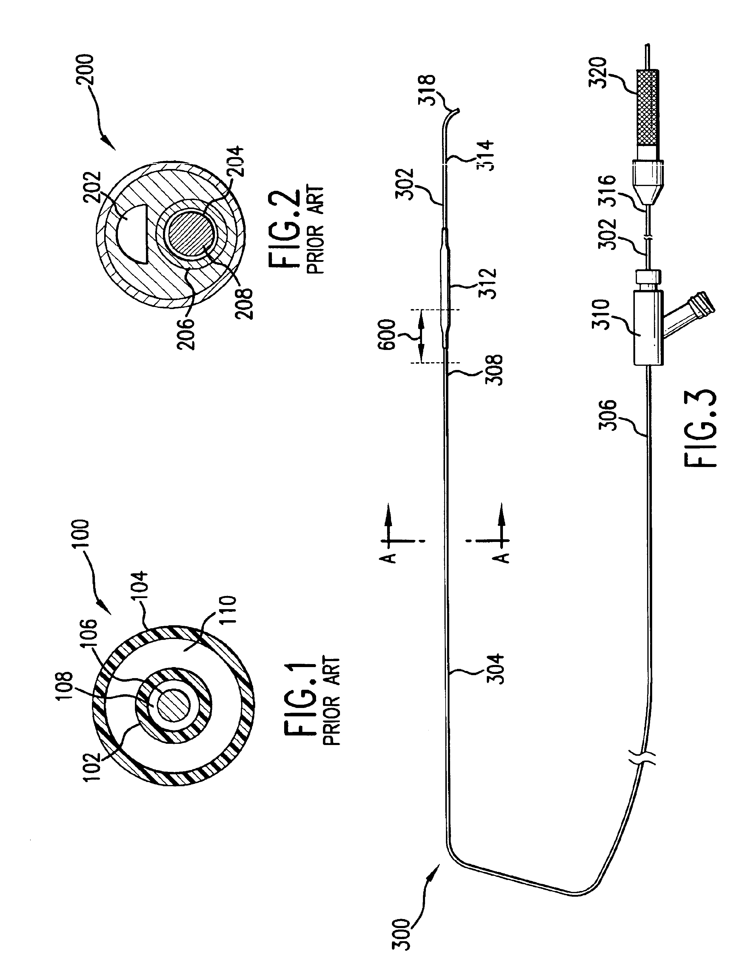
[0051]Referring first to FIG. 3, an embodiment of a dilatation catheter 300 and a guidewire 302 are shown. Dilatation or balloon catheter 300 includes a catheter shaft 304 having a proximal end 306 and a distal end 308. Proximal end 306 of catheter shaft 304 is secured to a luer hub 310. Distal end 308 of catheter shaft 304 is attached to a dilatation balloon 312. An interior of balloon 312 is in fluid communication with an external source of inflation fluid through the length of catheter shaft 304.

[0052]Balloon 312 is formed of a thin, pliable material capable of expandi...


PUM


Abstract

A catheter shaft for a catheter includes a centrally-located guidewire lumen. A body portion of the catheter shaft includes arc-shaped nodes that define a guidewire track within the guidewire lumen. The nodes include a crown region that includes a single contact point for the guidewire and may be formed of a material having a lower coefficient of friction. At least one node has an inflation lumen extending therethrough. The catheter shaft has a cut in it extending radially from the guidewire lumen to an exterior surface of the catheter shaft. The balloon catheter has a guide member that opens the cut and tracks the guidewire in and out of the catheter shaft along a length of the catheter shaft which is cut.

Description

BACKGROUND OF THE INVENTION[0001]1. Field of the Invention[0002]This invention relates generally to a medical device. More specifically, the invention relates to a catheter for insertion over a guidewire through a patient's vasculature, the catheter having a low friction guidewire lumen.[0003]2. Background of the Invention[0004]Cardiovascular disease, including atherosclerosis, is the leading cause of death in the U.S. The medical community has developed a number of methods and devices for treating coronary heart disease, some of which are specifically designed to treat the complications resulting from atherosclerosis and other forms of coronary arterial narrowing.[0005]One method for treating atherosclerosis and other forms of coronary narrowing is percutaneous transluminal coronary angioplasty, commonly referred to as “angioplasty” or “PTCA”. The objective in angioplasty is to enlarge the lumen of the affected coronary artery by radial hydraulic expansion. The procedure is accompl...

Claims


Application Information

Patent Timeline
Patent Type & Authority Patents(United States)
IPC IPC(8): A61M25/10A61M25/00A61F2/958A61M25/09
CPCA61M25/0023A61M25/0032A61M25/10A61M25/0009A61M2025/0034A61M2025/0036A61M2025/0062
Inventor KANTOR, JOHN D.
Owner MEDTRONIC VASCULAR INC
Why Eureka
Try Eureka