Catheter and medical tube

a catheter and medical technology, applied in the direction of balloon catheters, dilators, surgery, etc., can solve the problems of reducing the effect of preventing occurrence of kink, difficult to smoothly transmit pushing force, and prone to front portion kink, etc., to suppress occurrence of kink, no rapid change of rigidity, and excellent pushability and trackability.

Active Publication Date: 2011-10-25
TERUMO KK
View PDF19 Cites 22 Cited by
  • Summary
  • Abstract
  • Description
  • Claims
  • Application Information

AI Technical Summary

Benefits of technology

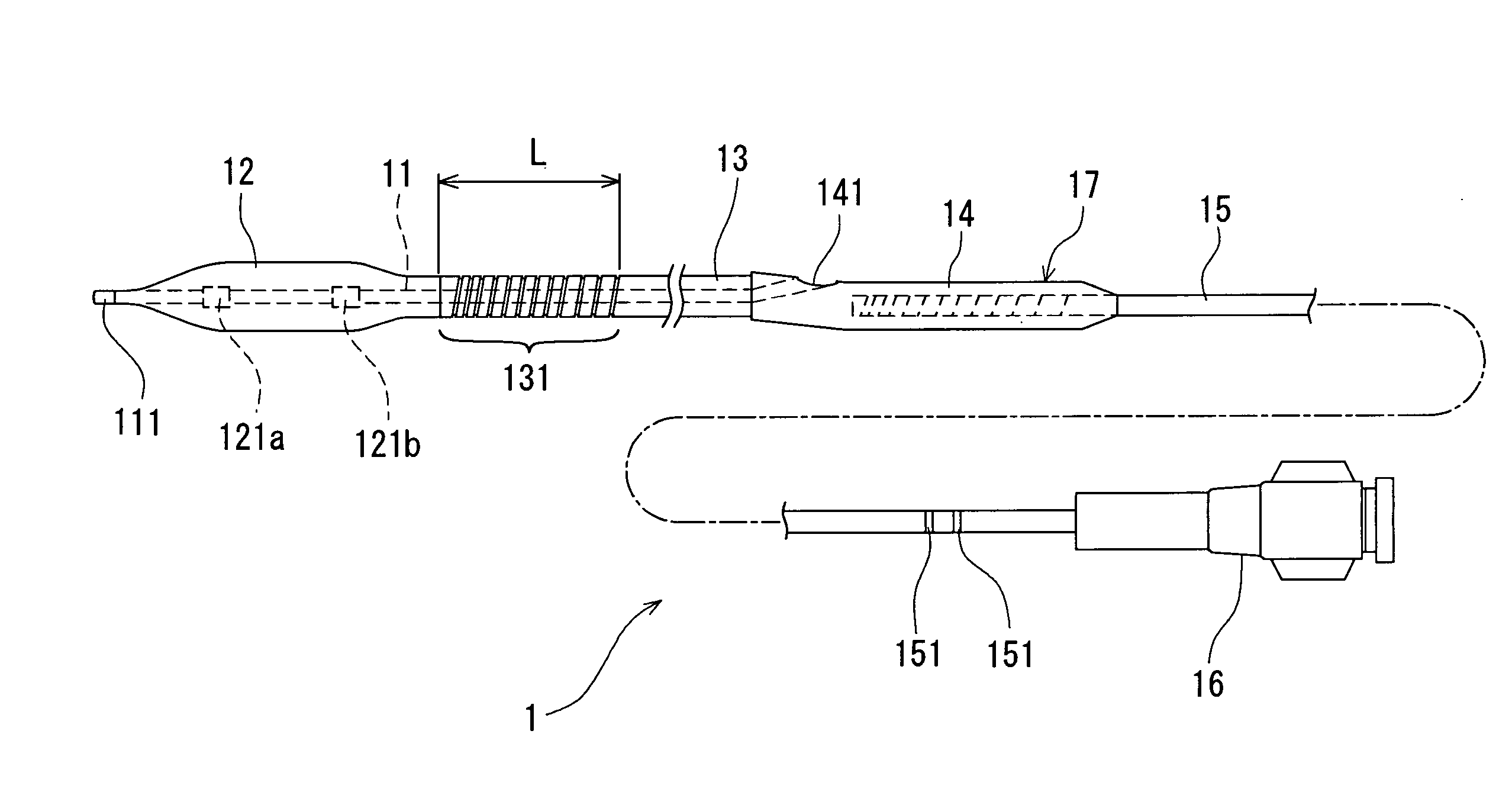
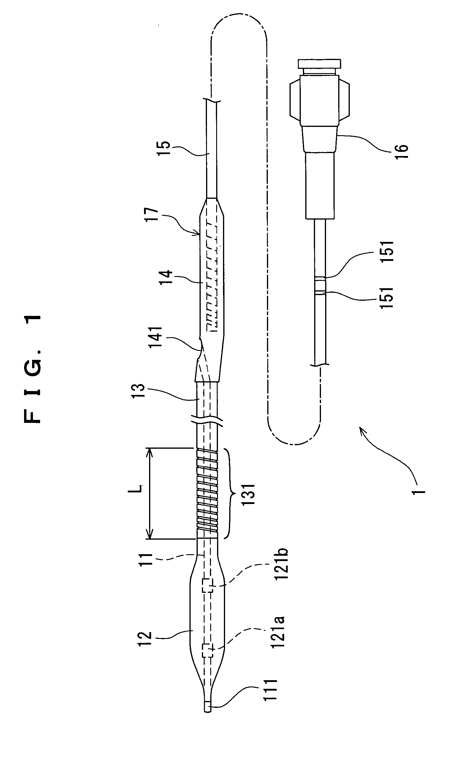
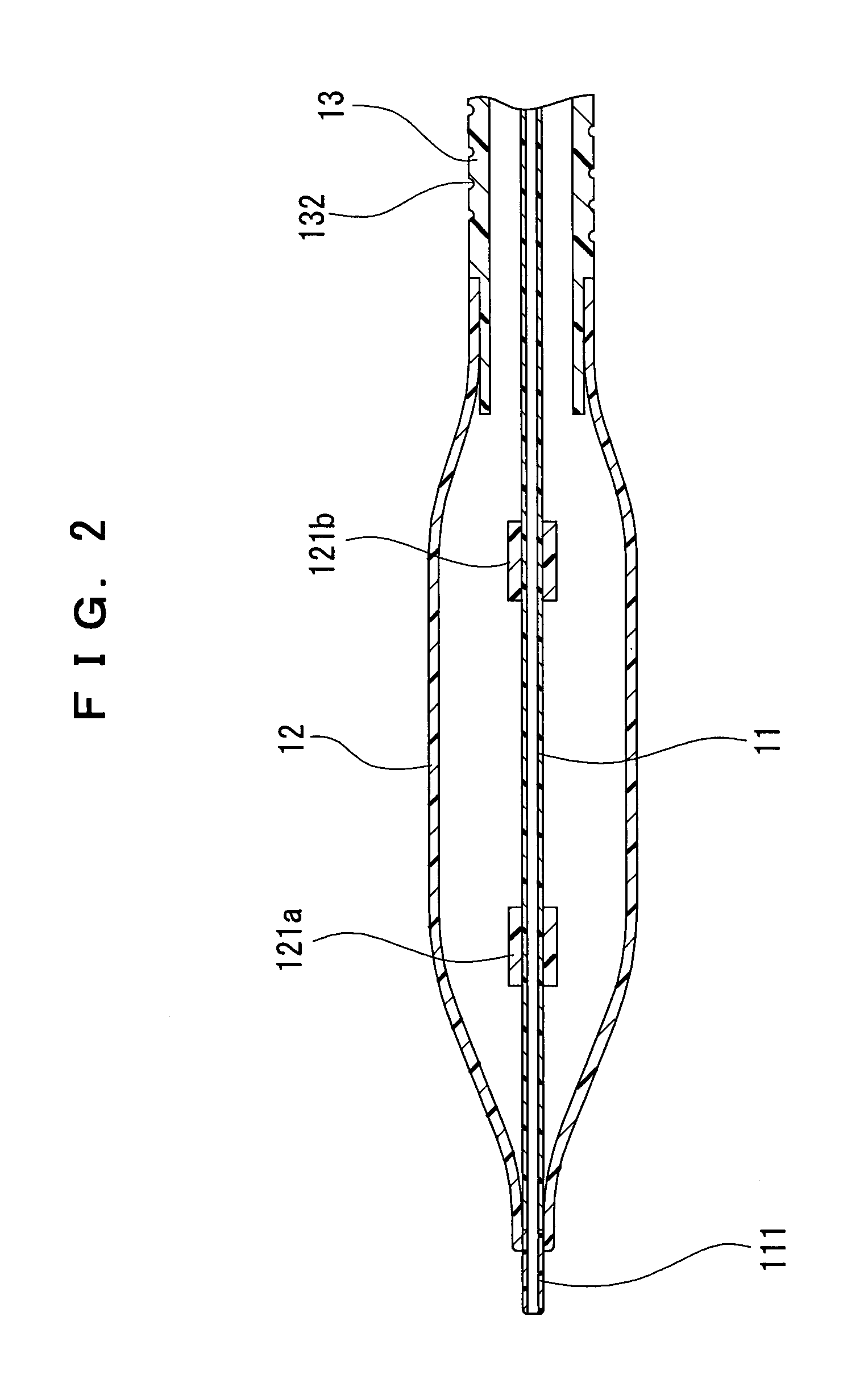
[0013]The catheter of the present invention having the above-described configuration is advantageous in being excellent in pushability, trackability, torque transmission performance, and kink resistance, and having flexibility at the front portion of the catheter, and is also advantageous in being capable of suppressing occurrence of kink, thereby reaching a more peripheral target cite of a living body because the distal shaft has no rapid change point of rigidity and exhibits the rigidity (physical property) smoothly changed in the longitudinal direction. In particular, the balloon catheter of the present invention is advantageous in being capable of suppressing occurrence of kink in a front portion, adjacent to a balloon, of a shaft main body, thereby smoothly reaching a more peripheral vascular vessel or other living lumen.
[0014]The medical tube of the present invention having the above-described configuration is advantageous in being excellent in pushability, trackability, torque transmission performance, and kink resistance, and having a flexibility at the front portion of the tube-like shaft, and is also advantageous in being capable of suppressing occurrence of kink, thereby reaching a more peripheral target cite of a living body because the tube-like shaft has no rapid change point of rigidity and exhibits the rigidity (physical property) smoothly changed in the longitudinal direction.
[0015]The catheter and the medical tube of the present invention have a further advantage that since the rigidity (physical property) can be more smoothly changed by changing the pitch or depth of a groove or grooves in the longitudinal direction of a grooved portion or combining the changes in pitch and depth of the groove or grooves with each other, each of the catheter and the medical tube is capable of significantly suppressing occurrence of kink, thereby easily reaching a more peripheral vascular vessel or other living lumen.
[0016]In addition, according to the present invention, the steps of producing each of the catheter and the medical tube are simpler than the prior art steps of connecting shafts having different rigidities or changing the wall thickness or outer diameter of the shaft by extrusion molding.

Problems solved by technology

In the case of connecting the shaft portions having different rigidities, however, it fails to obtain a smooth change in rigidity, and therefore, there occurs a problem that stress is concentrated at the boundary (interface) of the connection portion, thereby tending to cause kink.
Also, there occurs a problem that in the case of advancing a vasodilatation balloon catheter along a meandering blood vessel to a stricture generated in a peripheral vascular vessel such as a coronary artery, kink is liable to occur at a front portion, adjacent to the balloon, of the shaft main body.
The occurrence of such kink makes it difficult to smoothly transmit a pushing force given at the proximal end of the catheter to the distal end of the catheter and hence to push the catheter to a more peripheral vascular vessel.
However, since the shaft is generally produced by extrusion molding, there arises a problem that an extrusion speed upon extrusion from a die, an extruded amount of a resin material, and the like must be accurately controlled to change the outer diameter or wall thickness of the shaft by extrusion molding, and therefore, the skillful technique is required for production of the shaft.
Additionally, in the case of preventing occurrence of kink only by changing the outer diameter or wall thickness of the shaft, the effect of preventing occurrence of kink has a limitation.

Method used


Image

  • Catheter and medical tube
  • Catheter and medical tube
  • Catheter and medical tube

Examples


example

[0103]A nylon tube (Shore D hardness: 72, flexural modulus: 11,175 kgf / cm2) having an outer diameter of 0.9 mm and a wall thickness of 85 μm was formed by covering a copper wire with nylon by extrusion molding, to produce a distal shaft. A spiral groove was then formed in the distal shaft by the following spiral groove forming process. In this process, the copper wire used for extrusion molding was used as a core member.

[0104]Both ends of the distal shaft were chucked, and one end of a metal fine wire (material; tungsten) having an outer diameter of 60 μm was fixed in the vicinity of the distal shaft. The distal shaft was rotated at a rotational speed of 300 rpm in the circumferential direction and simultaneously displaced at a movement speed of 60 mm / min in the longitudinal direction. In such a state, the fine wire was fed from a fine wire supply unit with a tension applied thereto in the direction perpendicular to the longitudinal direction of the shaft, to be wound around the dis...


PUM


Abstract

A catheter includes a proximal shaft having a relatively high rigidity, a distal shaft provided on a front portion of the proximal shaft so as to be in fluid communication with proximal shaft and having a rigidity lower than that of the proximal shaft, a hub mounted to the vicinity of a rear end of the proximal shaft and configured to allow a pressure applying apparatus to be mounted to the hub, and a balloon provided on a front portion of the distal shaft so as to be in fluid communication with the distal shaft and configured to receive pressure applied from the hub. The catheter also includes a guide wire lumen. In this catheter, at least a front portion of the distal shaft is configured as a grooved portion having a groove or grooves.

Description

BACKGROUND OF THE INVENTION[0001]The present invention relates to a diagnostic or therapeutic catheter for performing various treatments in blood vessels and a medical tube used for endoscopes and the like. In particular, the present invention relates to a dilatation balloon catheter used for treating a stricture generated in a lumen such as a blood vessel by dilating the stricture, thereby improving the flow of blood in a peripheral side of the stricture, and a living organ dilatation catheter capable of delivering a living organ dilatation stent to a target living organ cite with a safety and a smooth operationality.[0002]In recent years, functions of medical tubes have been significantly enhanced. Examples of such high function medical tubes include a vasodilatation balloon catheter used for percutaneous transluminal angioplasty for dilating a stricture in a blood vessel; a living organ dilatation catheter capable of delivering a living organ dilatation stent to a target living o...

Claims


Application Information

Patent Timeline
Patent Type & Authority Patents(United States)
IPC IPC(8): A61M25/00A61M29/00A61M29/02
CPCA61M25/0054A61M25/104A61M2025/0183A61M2025/1061
Inventor HISAMATSU, TAKATOMOSOMA, KATSUAKISEKINO, MASAKIKOBAYASHI, JUNICHI
Owner TERUMO KK
Why Eureka
Try Eureka