
Tube structure

a technology of tubes and tubes, applied in the field of tubes, can solve the problems of easy kink or fold easy kinking or folding of traditional medical catheters, and easy kinking of liquid flowed inside the medical catheter after implanting into the human body, etc., to achieve excellent puncture resistance, reduce the existence of kink phenomenon, and excellent kink resistance

Pending Publication Date: 2022-06-16
COATING P MATERIALS CO LTD
View PDF3 Cites 0 Cited by
  • Summary
  • Abstract
  • Description
  • Claims
  • Application Information

AI Technical Summary

Benefits of technology

The invention provides a tube structure that improves its resistance to kinking and puncturing. The structure includes a wire surrounding the outer surface of the tube body to form multiple wire gaps. These gaps create a first wiring density, a third wiring density, and a second wiring density on different sections of the tube. The first wiring density is lower than the third, and the second is lower than the third, which results in excellent kink resistance and puncture resistance. This makes the tube structure less likely to develop kinking or puncturing issues when folded or punctured.

Problems solved by technology

However, these traditional medical catheters do not possess good kink resistance.
The traditional medical catheter can be easily kinked or folded by squeezing, and the liquid flowed inside the medical catheter after implanting into the human body can also be easily affected.
However, as the traditional medical catheters do not possess good puncture resistance, the bleeding may easily occur when the injection time increases on the medical catheter.

Method used


Image

  • Tube structure
  • Tube structure
  • Tube structure

Examples


Embodiment Construction

[0021]The advantages and characteristics of the invention and the way to achieve the purpose of the invention will be easily understood by referring to the exemplary embodiments and the drawings. However, the invention can be embodied by different forms and should not be understood that the embodiments herein are limited to the invention. On the contrary, for persons ordinarily skilled in the art, the provided embodiments will express the scope of the present invention more thoroughly, more wholly and more completely.

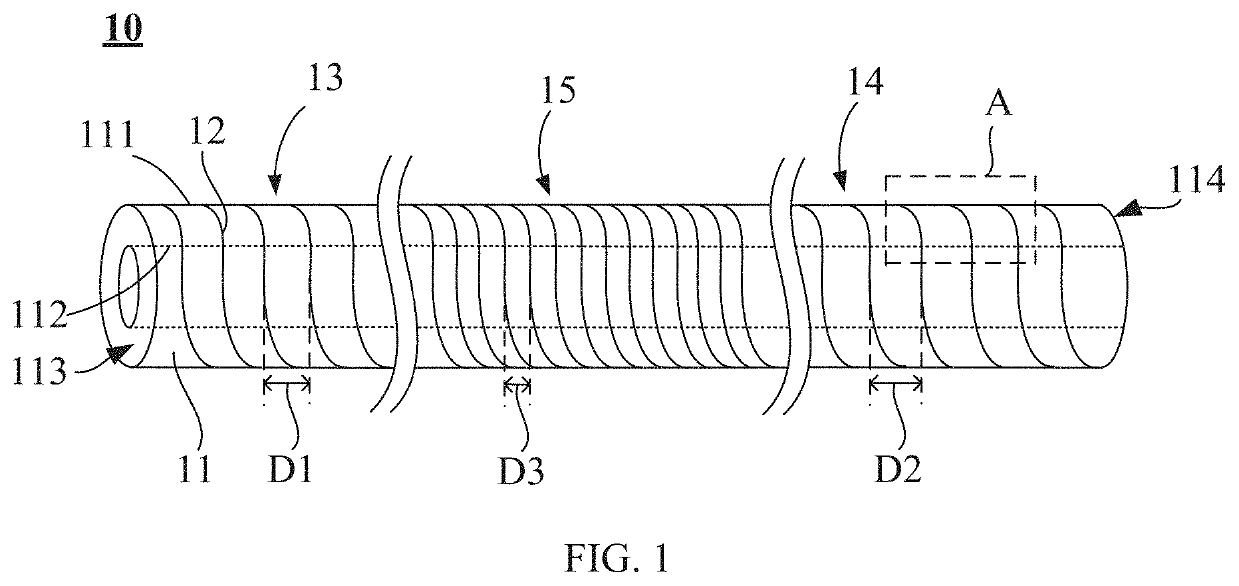
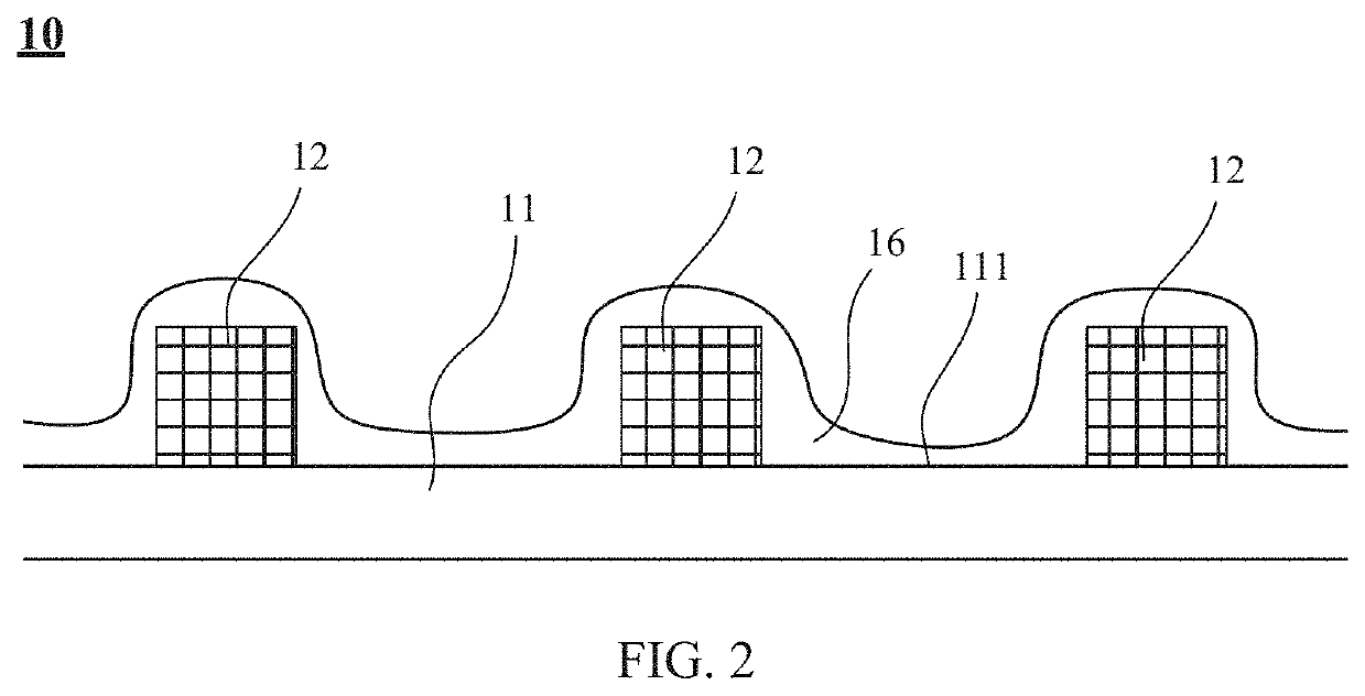
[0022]FIG. 1 is a schematic view of the tube structure in accordance with one embodiment of the invention. Please refer to FIG. 1. The tube structure 10 includes a tube body 11 and a wire 12, where the tube body 11 is formed by polyurethane (PU) elastomer and can be use as vascular prosthesis. The tube body 11 includes an outer surface 111, an inner surface 112, a first end 113, and a second end 114 opposite to the first end 113. The outer surface 111 is opposite to the...


PUM

PropertyMeasurementUnit
Lengthaaaaaaaaaa
Thicknessaaaaaaaaaa
Diameteraaaaaaaaaa

Abstract

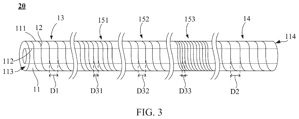
A tube structure includes a tube body formed by polyurethane elastomer and a wire. The tube body includes an outer surface, a first end, and a second end opposite to the first end. The outer surface is connected to the first end and the second end and the outer surface is surrounded around by the wire to form a plurality of wire gaps. A first implanting section, a connecting section, and a second implanting section are sequentially disposed from the first end to the second end of the tube body. So the plurality of wire gaps respectively form with a first wire-surrounding density, a third wire-surrounding density, and a second wire-surrounding density at the first implanting section, the connecting section and the second implanting section, wherein the first wire-surrounding density is less than the third wire-surrounding density, and the second wire-surrounding density is also less than the third wire-surrounding density.

Description

FIELD OF THE INVENTION[0001]The present invention relates to a tube structure, more particularly to a tube structure is capable of kink and puncture resistance simultaneously.BACKGROUND OF THE INVENTION[0002]Medical catheters, such as vascular prosthesis, are substitutions for thrombosis or angiostenosis of native blood vessels. The medical catheters are made by nylon in early days and polytetrafluoroethylene (PTFE) presently, where expanded PTFE (ePTFE) is more common. The main manufacturing method of the ePTFE catheter is expanded-elongation method, and presently the ePTFE catheters have been applied on therapies of diseases on artery or vein.[0003]The medical catheters always need to engage a plurality of obstacles such as other tissues, blood vessels or organs near the affected region when the medical catheters are implanted or applied into the human body or other experimental bodies. However, these traditional medical catheters do not possess good kink resistance. The tradition...

Claims


Application Information

Patent Timeline
IPC IPC(8): A61M25/00C08L75/04C08L67/02C08L67/04
CPCA61M25/005A61M25/0023A61M2205/0216C08L67/02C08L67/04C08L75/04A61M25/0053A61L31/06A61L2430/36
Inventor CHANG, CIN-HELIN, YUNG-TAI
Owner COATING P MATERIALS CO LTD
Learn More