Guide wire

a technology of guide wire and distal end, which is applied in the direction of guide wires, catheters, applications, etc., can solve the problems of difficult to meet the requirements of flexibility and operationality, difficult to use a single material core member, and limited control of the flexibility of the distal end portion by heat treatment, etc., to improve the operationality of the guide wire and the catheter, shorten the operation time, and improve the safety

Active Publication Date: 2007-08-30
TERUMO KK
View PDF44 Cites 21 Cited by
  • Summary
  • Abstract
  • Description
  • Claims
  • Application Information

AI Technical Summary

Benefits of technology

[0034] Since the projection is provided at the welded portion between the first wire and the second wire, the welded portion becomes easily visible under fluoroscopy, to improve the operationality of the guide wire and a catheter used together with the guide wire, thereby shortening the operation time and improving the safety.
[0035] The provision of the projection is also effective in reducing the contact area of the guide wire with the inner wall of a catheter used together with the guide wire, to reduce the friction resistance of the guide wire during movement of the guide wire relative to the catheter, thereby improving the sliding performance. As a result, it is possible to enhance the

Problems solved by technology

The guide wire including such a core member, however, has an inconvenience that the distal end portion of the guide wire becomes lower in flexibility.
In this way, it has been regarded as difficult to satisfy both requirements associated with the flexibility and operationality by using a core member made from a single material.
Such a gu

Method used


Image

  • Guide wire
  • Guide wire
  • Guide wire

Examples


Embodiment Construction

[0053] A guide wire of the present invention will now be described in detail by way of preferred embodiments shown in the accompanying drawings.

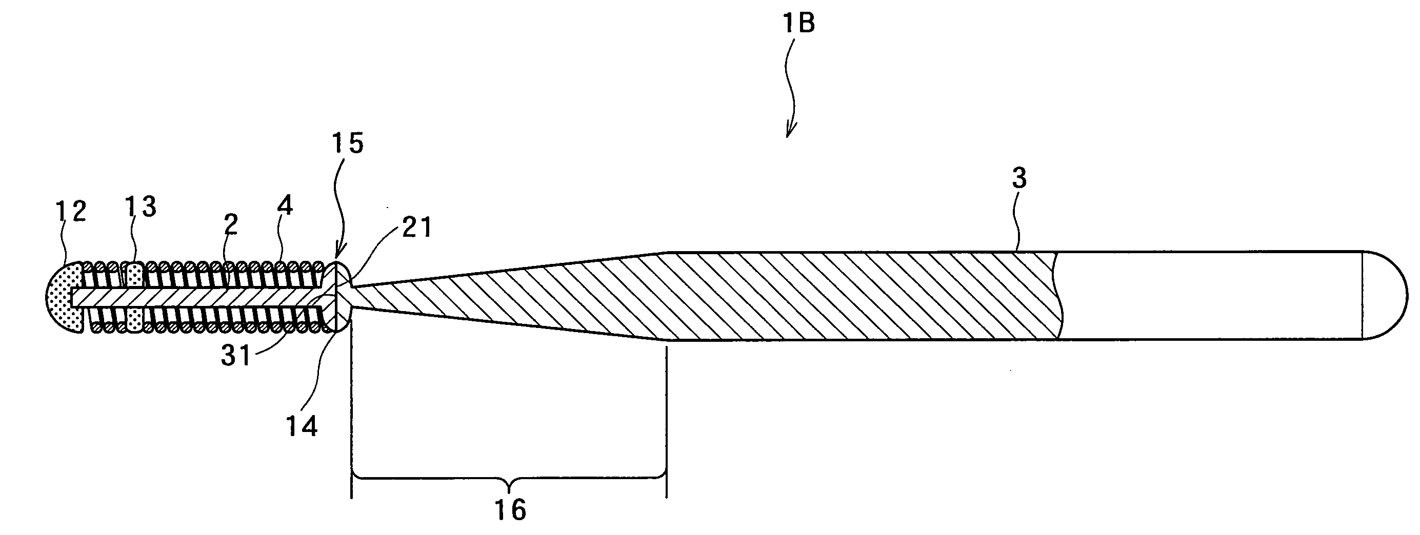
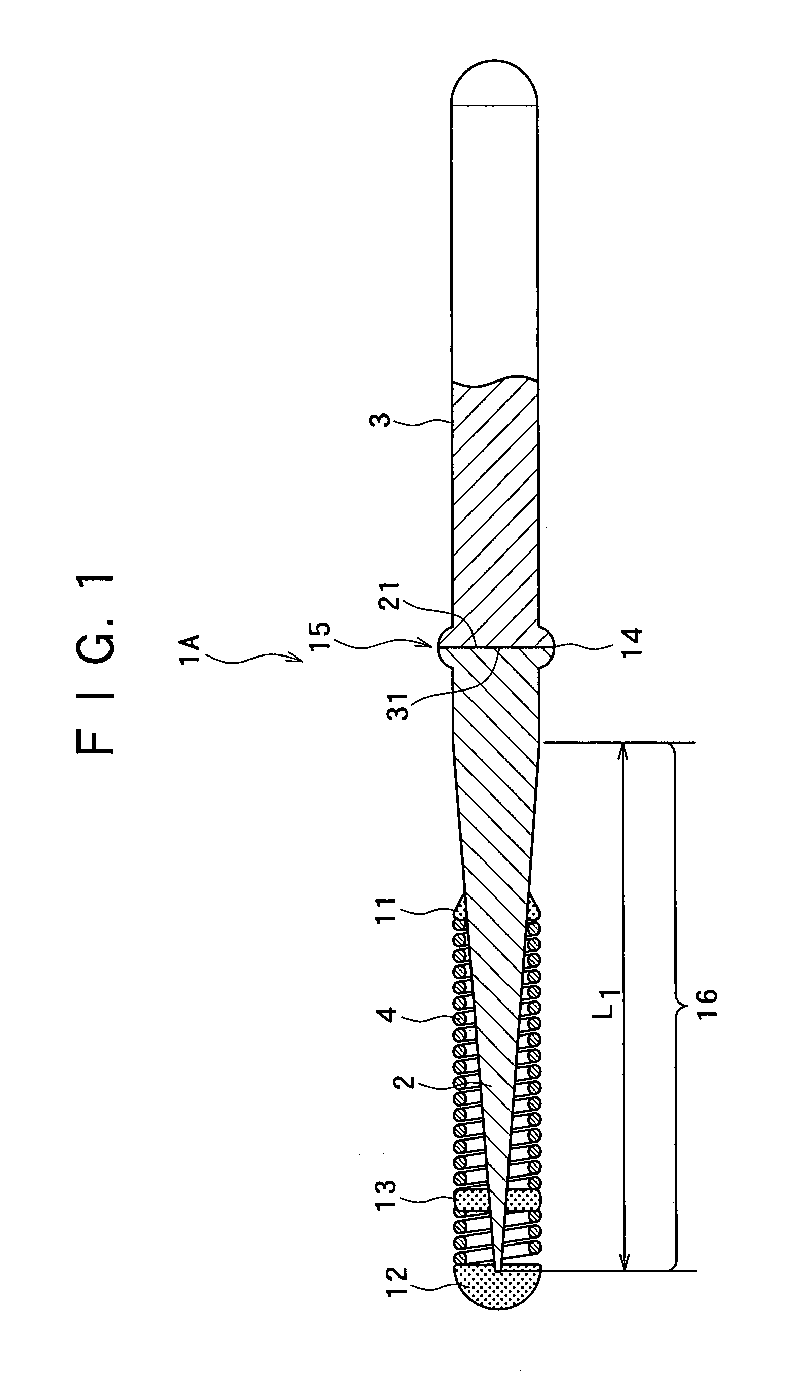
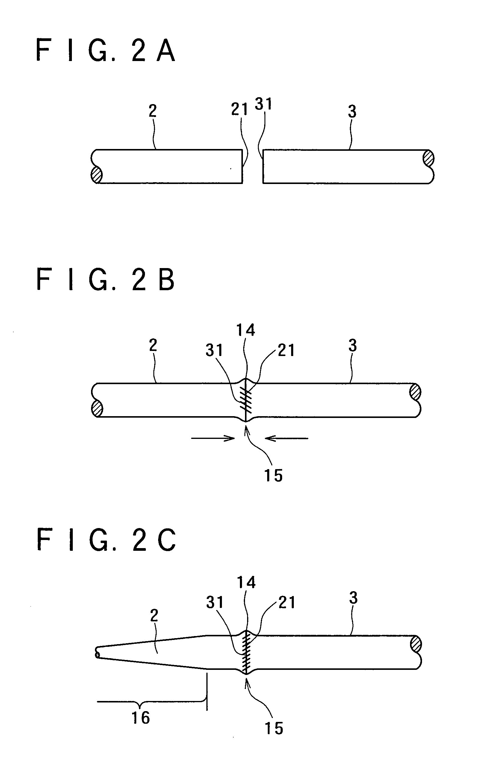
[0054]FIG. 1 is a longitudinal sectional view of a first embodiment of a guide wire of the present invention, and FIGS. 2A to 2C are views showing a procedure for joining a first wire and a second wire of the guide wire shown in FIG. 1 to each other. For convenience of description, the right side in FIG. 1 is taken as the “proximal side” and the left side in FIG. 1 is taken as the “distal side”. It is to be noted that in FIG. 1 and FIGS. 2A to 2C (and in FIGS. 5 to 9 to be described later), for easy understanding, the dimension of the guide wire in the thickness direction is exaggeratedly enlarged while the dimension of the guide wire in the length direction is shortened, and therefore, the ratio of the thickness to the length is significantly different from the actual ratio.

[0055] A guide wire 1A shown in FIG. 1, which is of a type used t...


PUM

PropertyMeasurementUnit
Diameteraaaaaaaaaa
Electric potential / voltageaaaaaaaaaa
Dimensionaaaaaaaaaa

Abstract

A method of making a guide wire involves butting a connection end face at a proximal end of a first wire against a connection end face at a distal end of a second wire while applying voltage and a pressing force to weld together the first and second wires at a welded portion. The welded portion forms a projection that projects outwardly in an outer peripheral direction relative to portions of the first and second wire adjacent the projection. The outer dimension of the projection at the welded portion is adjusted so that upon completing adjusting the outer dimension of the projection the projection still projects outwardly in the outer peripheral direction relative to the portions of the first and second wire adjacent the projection.

Description

[0001] This application is a divisional of U.S. application Ser. No. 10 / 635,712 filed on Aug. 7, 2003 which serves as the basis for a claim for priority under 35 U.S.C. §120 in this application, the entire content of which is incorporated herein by reference.BACKGROUND OF THE INVENTION [0002] 1. Field of the Invention [0003] The present invention relates to a guide wire, particularly to a guide wire used to guide a catheter in a body lumen such as a blood vessel. [0004] 2. Description of the Related Art [0005] Guide wires are used to guide a catheter in treatment of cites at which open surgeries are difficult or which require minimally invasiveness to the body, for example, PTCA (Percutaneous Transluminal Coronary Angioplasty), or in examination such as cardio-angiography. A guide wire used in the PTCA procedure is inserted, with the distal end projecting from the distal end of a balloon catheter, into the vicinity of a target angiostenosis portion together with the balloon catheter...

Claims


Application Information

Patent Timeline
IPC IPC(8): F16L11/14A61M25/01A61B5/00A61M25/09
CPCA61M25/09A61M2025/09108A61M2025/09083
Inventor MURAYAMA, HIRAKUUMENO, AKIHIKOIWAMI, JUNITOU, YUTAKAAIMI, YOUKI
Owner TERUMO KK
Why Eureka
Try Eureka