Unison ring assembly for an axial compressor casing

a compressor and unison ring technology, applied in the direction of machines/engines, reaction engines, liquid fuel engines, etc., can solve the problems of unsatisfactory unison ring clearance, exasperated clearance variation, and running clearance variation, so as to reduce friction and wear of contact surfaces, eliminate any redundant movement, and facilitate the effect of minimal friction and even wear

Inactive Publication Date: 2012-02-28
SIEMENS AG
View PDF14 Cites 24 Cited by
  • Summary
  • Abstract
  • Description
  • Claims
  • Application Information

AI Technical Summary

Benefits of technology

[0016]The exponential force required to compress the resilient member within the unison ring assembly results in ready accommodation of relatively small diametric differential between the compressor casing and the unison ring diameter while still opposing greater magnitudes of compression from the external drive faun that is required to rotate the unison ring.
[0018]By positioning three slide bearings equi-spaced around the unison ring, the result is an equalisation of the compression force relative to each other individual slide bearing. This in effect ensures that the unison ring is always positioned concentric to the inner diameter and therefore rotate concentrically about it. Further, the slide bearings offer minimal friction to enable the contacting surfaces to slide freely.
[0019]The positioning of three unison ring supports equi-spaced around the unison ring provides equalization of the compression form relative to each other individual unison ring support. This in effect will ensure that the unison ring is consistently positioned concentric to the casing diameter that it rotates about. Consistent concentric rotation of the unison ring about the compressor case diameter irrespective to the assembly components thermal growth or operational surface wear ensures each variable guide vane lever is actuated equally around the whole unison ring circumference. The maintained contact between the unison ring slipper pads and the compressor case eliminates any redundant movement of the unison ring.
[0020]Preferably, the slide bearing is profiled to match the outer diameter of the compressor casing. Therefore, even load distribution against the compressor casing is ensured. This assists minimal friction and even wear of the contacting surfaces.
[0022]The elastic material when compressed provides expansion to maintain constant contact of the slide bearing against the casing. Expansion of the elastic material will accommodate mechanical wear of the contact surfaces and initial machined tolerance variation of the unison ring assembly against the compressor casing. The elastic material components can also compress to accommodate the differential diameters of the expanding compressor casing relative to the unison ring. The elastic material exhibits a steeply exponential force requirement to compress offering the advantage that small ratios of compression caused by differential thermal expansions and manufacturing tolerances are readily accommodated whilst also resisting larger external unison ring driving forces.
[0030]The compression screw incorporated by the slide bearing facilitates the unison ring assembly by initially compressing and clamping together the resilient member to offer exaggerated diametric clearance. Once the complete unison ring has been positioned about the compressor case each compression screw is loosened.

Problems solved by technology

Temperature induced expansion differences between the compressor casing and the unison ring result in running clearance variations.
Clearance variation is also exasperated when factoring in machining tolerances of the assembled components and operational wear between the contacting components.
This means that for the nominal constant running condition the unison ring clearance is not optimal.
Clearance between the slide bearings of the unison ring and their contact surface, the compressor casing, results in redundant movement when an external force is applied to rotate the unison ring about the compressor casing.

Method used


Image

  • Unison ring assembly for an axial compressor casing
  • Unison ring assembly for an axial compressor casing
  • Unison ring assembly for an axial compressor casing

Examples


Embodiment Construction

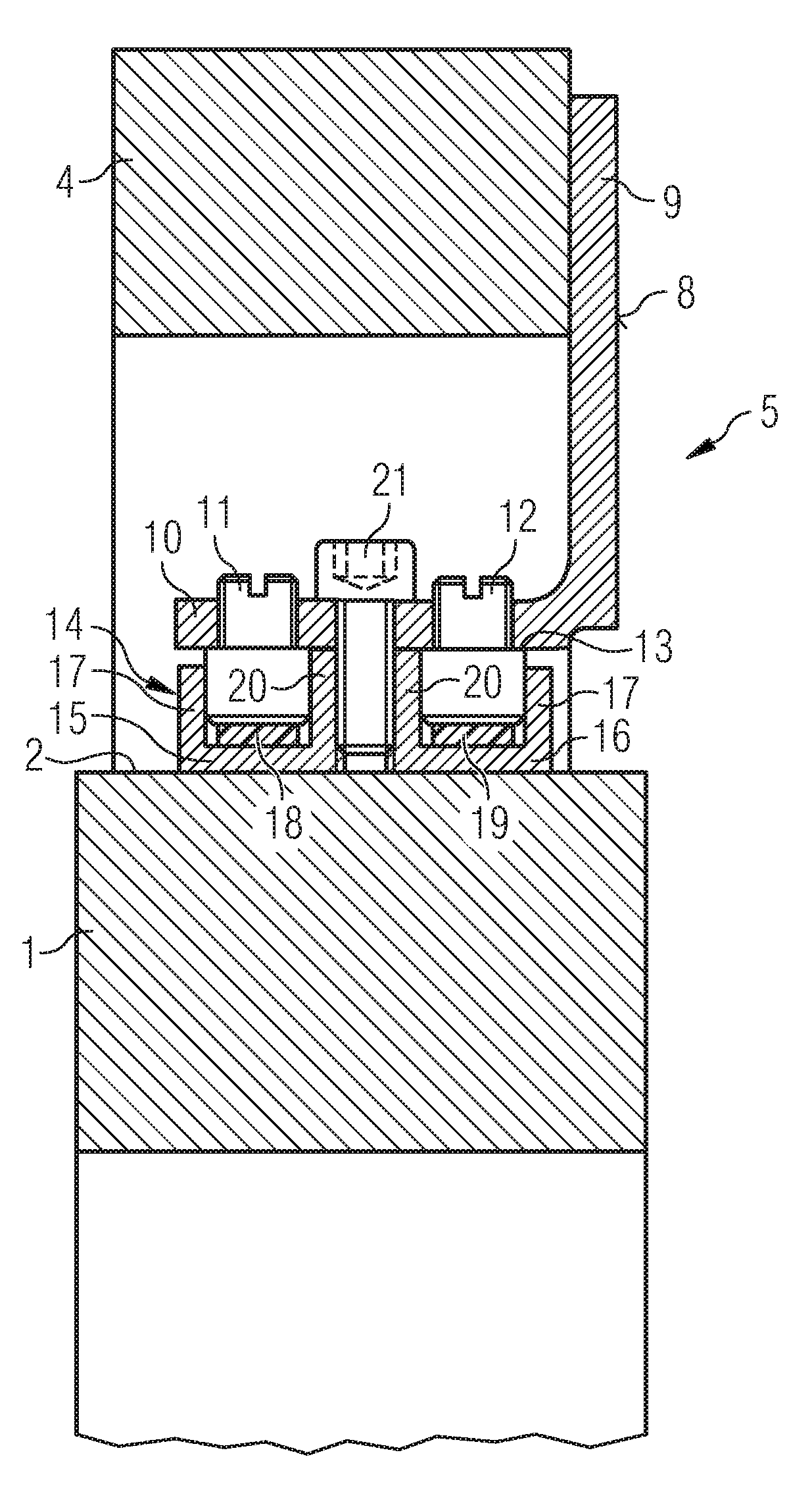
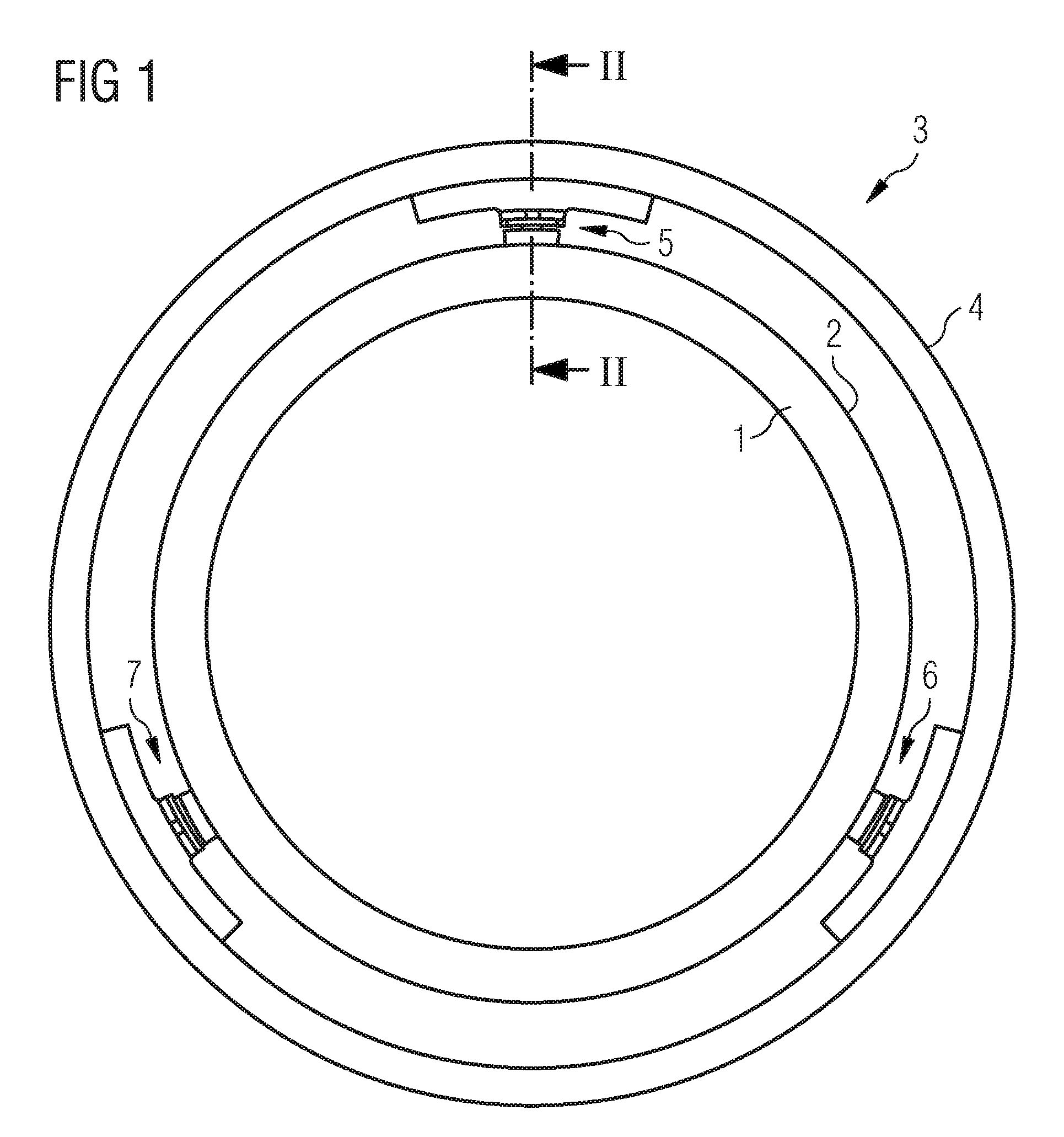
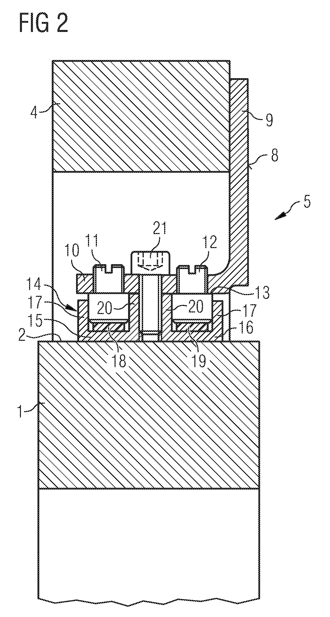
[0035]FIGS. 1 and 2 show an axial compressor casing 1 comprising a unison ring assembly 3 arranged concentrically around a slide face of the outer surface of the compressor casing 1. The unison ring assembly 3 comprises a unison ring 4 and three unison ring supports 5, 6, 7 being radial inwardly and equally spaced arranged along the circumference of the unison ring 4. Each unison ring support 5, 6, 7 comprises an unison ring bracket 8, wherein the unison ring bracket 8 is formed by a unison ring bracket fixation leg 9 and a unison ring bracket slide leg 10, together forming a L-form of the unison ring bracket 8.

[0036]Further, each unison ring support 5, 6, 7 comprises a slide bearing 14 for sliding along a slide face 2 of the outer surface of the compressor casing, and a resilient member being arranged between and coupled to the slide bearing 14 and the unison ring bracket sliding leg 10, such that the unison ring 4 is rotatable around the compressor casing 1 by sliding the slide be...


PUM


Abstract

A unison ring assembly for an axial compressor casing is provided. The unison ring assembly includes a unison ring and at least three unison ring supports being radial inwardly and equally spaced arranged along a circumference of the unison ring, wherein each unison ring support has a unison ring bracket attached to the unison ring. Further, the unison ring assembly includes a slide bearing to be sliding along a slide face of an outer surface of the compressor casing and a resilient member being arranged between and coupled to the slide bearing and the unison ring bracket such that the unison ring is rotatable around the compressor casing by sliding the slide bearing along the slide face and to be centered free of clearance about the compressor casing. The resilient member is adapted to accommodate radial displacement of the compressor casing.

Description

CROSS REFERENCE TO RELATED APPLICATIONS[0001]This application is the U.S. National Stage of International Application No. PCT / EP2009 / 052188 filed Feb. 25, 2009, and claims the benefit thereof. The International Application claims the benefits of European Patent Application No. 08006509.7 EP filed Mar. 31, 2008. All of the applications are incorporated by reference herein in their entirety.FIELD OF INVENTION[0002]The invention relates to a unison ring assembly for an axial compressor, an axial compressor comprising the unison ring assembly, and a method for mounting the unison ring assembly on the axial compressor casing.BACKGROUND OF INVENTION[0003]A gas turbine comprises a turbine and a compressor driven by the turbine. In particular, when the gas turbine is provided for a gas-steam power plant, the compressor is of the axial flow type. Commonly, the gas turbine is subjected to varying operating conditions resulting in different aerodynamic flow conditions within the compressor. In...

Claims


Application Information

Patent Timeline
Patent Type & Authority Patents(United States)
IPC IPC(8): F04D29/56
CPCF01D17/162F04D29/563F05D2240/54F05D2230/642
Inventor REDGWELL, PAUL
Owner SIEMENS AG
Why Eureka
Try Eureka