Synchronized spin multi-component projectile

a multi-component, projectile technology, applied in the field of projectiles, can solve the problems of non-synchronized spin and different components spinning in flight, and achieve the effect of reducing frictional engagement with rifling and increasing its kinetic energy

Active Publication Date: 2011-12-27
LIBERTY OPCO LLC
View PDF24 Cites 16 Cited by
  • Summary
  • Abstract
  • Description
  • Claims
  • Application Information

AI Technical Summary

Benefits of technology

Therefore, the tail drive and about one-half to two-thirds of the length of the cylindrical interface, including its middle and trailing extents, are the only parts of the projectile disposed in engaged relation to rifling when the projectile is disposed in a gun barrel. Accordingly, friction between the projectile and the rifling is reduced vis a vis a conventional projectile so that the novel projectile has increased kinetic energy when fired vis a vis a conventional projectile.
Another important object is to provide such a projectile that has reduced frictional engagement with rifling in a gun barrel to increase its kinetic energy when fired without substantially degrading the spin imparted by the rifling.
Still another important object of the invention is that the juncture of the head and tail portions meet at a point wherein inward axial force imparted by the rifling lands effectively crimp the interface to the head and tail portions to maintain each portion in synchronized rotation.

Problems solved by technology

This affects the inertia of each component and may result in differing components spinning in flight at different rates.
The fact of non-synchronized spin is a problem, regardless of what causes it.

Method used


Image

  • Synchronized spin multi-component projectile
  • Synchronized spin multi-component projectile
  • Synchronized spin multi-component projectile

Examples


Embodiment Construction

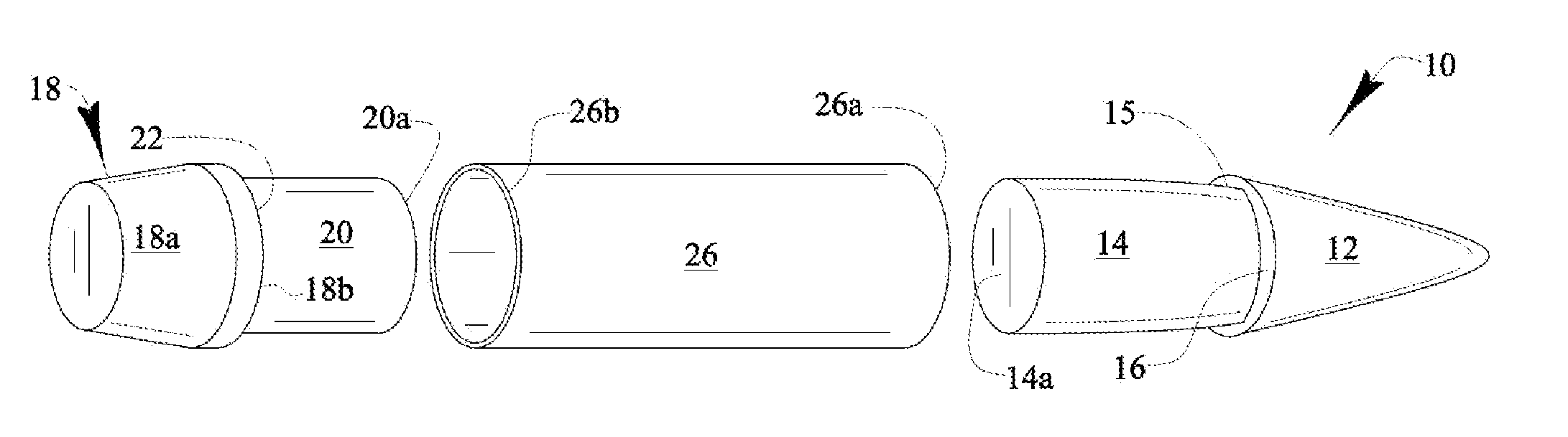
Referring now to FIG. 1, it will there be seen that a diagrammatic representation of the novel projectile is denoted as a whole by the reference numeral 10.

Novel projectile 10 includes a leading part formed by nose cone or ogive-shaped tip 12 and tip base 14 formed integrally with said tip. Tip base 14 is substantially cylindrical but a slight diameter-reducing taper 15 is formed in its leading extent where the leading end of tip base 14 meets the trailing end of tip 12. If tip base 14 were cylindrical with no taper, it would have a diameter less than the diameter of the trailing end of tip 14. However, with slight downward taper 15 formed in the leading extent of tip base 14, the difference in diameter is a little larger. The diameter difference creates first annular shoulder 16.

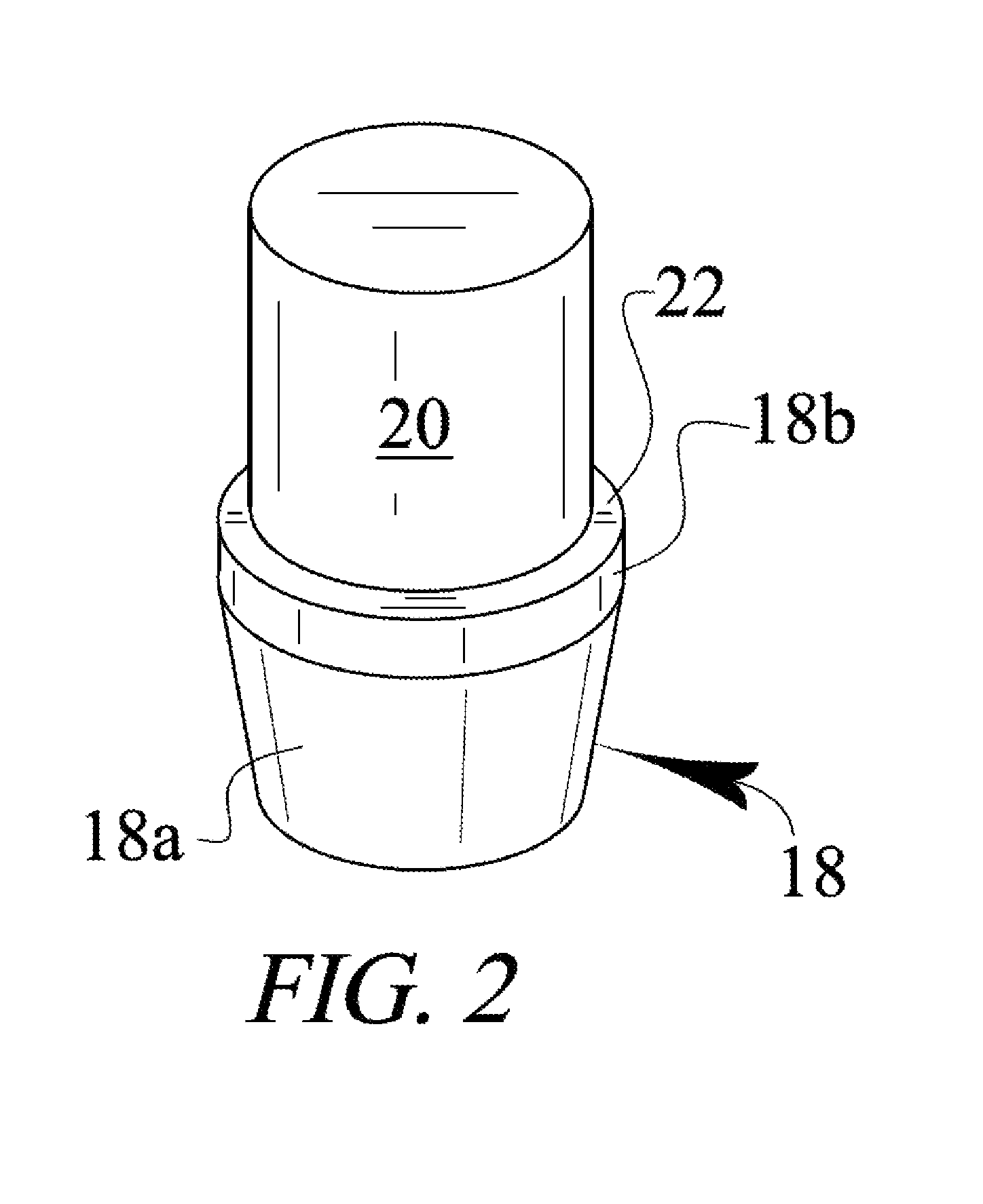
Novel projectile 10 further includes a trailing part formed by base 18 having a frusto-conical trailing end 18a and tail drive 18b. Cylindrical rod 20 is formed integrally with tail drive 18b. As perhaps be...


PUM


Abstract

A projectile includes a leading part formed by a tip and a tip base that form a first annular shoulder where they meet. A trailing part of the projectile is formed by a base having a frusto-conical trailing end and a cylindrical leading end of truncate extent that forms a tail drive. A second annular shoulder is formed where a cylindrical rod meets the tail drive. A flat trailing end of the tip base and a flat leading end of the cylindrical rod abut one another when the projectile is assembled. A cylindrical interface has a leading extent abutting the first annular shoulder and a trailing end abutting the second annular shoulder. The tail drive and the trailing extent of the cylindrical interface are the only parts of the projectile that engage gun barrel rifling when the projectile is positioned in a gun barrel.

Description

BACKGROUND OF THE INVENTION1. Field of the InventionThis invention relates, generally, to the art of projectiles. More particularly, it relates to a multi-component projectile having components that spin at a common rate as if the projectile were formed of a single component.2. Description of the Prior ArtThe components of a multi-component projectile may spin at independent rates as the projectile spins. Many factors may be involved including the fact that the different components may be made of different materials having different densities. This affects the inertia of each component and may result in differing components spinning in flight at different rates. Another important factor may be that the bonds between the various components may have differing strengths. The fact of non-synchronized spin is a problem, regardless of what causes it.However, in view of the art considered as a whole at the time the present invention was made, it was not obvious to those of ordinary skill i...

Claims


Application Information

Patent Timeline
Patent Type & Authority Patents(United States)
IPC IPC(8): F42B14/02F42B30/02
CPCF42B10/26F42B10/38F42B12/34F42B14/02
Inventor MARX, PJ
Owner LIBERTY OPCO LLC
Why Eureka
Try Eureka