Reduced friction projectile

a projectile and projectile technology, applied in the field of projectiles, can solve the problems of unpredictable alterations in the behavior of the projectile, the deformation of the projectile by the rifling in a way that is unpredictable, and the barrel to heat up with repeated firing, so as to reduce the frictional contact, reduce the friction, and reduce the friction created by the projectile's travel through the barrel

Inactive Publication Date: 2011-03-08
LIBERTY OPCO LLC
View PDF19 Cites 25 Cited by
  • Summary
  • Abstract
  • Description
  • Claims
  • Application Information

AI Technical Summary

Benefits of technology

[0015]The unsupported medial extent of the cylindrical interface is therefore deformed radially inwardly by lands in a barrel when the projectile is fired. The leading and trailing ends of the cylindrical interface maintain contact with the lands and the medial extent does not, thereby reducing friction between the projectile and the barrel without sacrificing the spin of the projectile imparted by the lands and grooves.
[0022]Thus it is understood that the respective cross-sectional configurations of the leading and trailing rods may be provided in any predetermined geometrical configuration and that the cylindrical interface will be deformed by the lands upon projectile firing so that the cylindrical interface conforms to the predetermined geometrical configuration of the leading and trailing rods. This advantageously reduces the frictional contact between the cylindrical interface and the rifling without affecting the contact between the leading and trailing parts of the projectile and the rifling. Thus, spin is still imparted to the projectile but the friction created by the travel of the projectile through the barrel is substantially reduced.
[0023]An important object of the invention is to reduce the friction between a projectile and the interior of a gun barrel to increase the kinetic energy of the projectile, to reduce heat build-up in the barrel caused by repeated rapid firing, and to deform the projectile in a predictable, consistent way.

Problems solved by technology

Nor has it recognized that the friction created by such substantially full-length engagement causes the barrel to heat up with repeated firing.
Nor has the art recognized that such substantially full-length engagement leads to deformation of the projectile by the rifling in a way that is unpredictable.
Such unpredictable deformation leads to unpredictable alterations in behavior of the projectile.

Method used


Image

  • Reduced friction projectile
  • Reduced friction projectile
  • Reduced friction projectile

Examples


Embodiment Construction

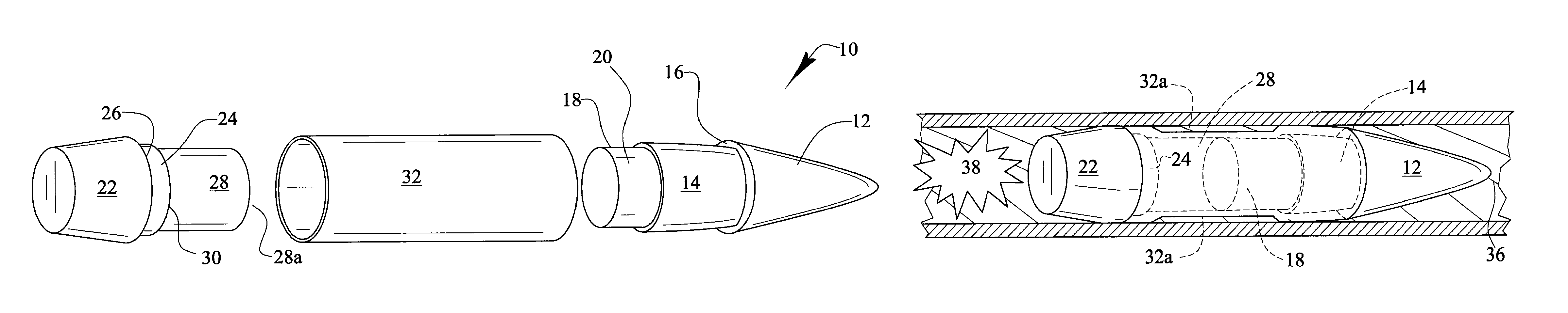
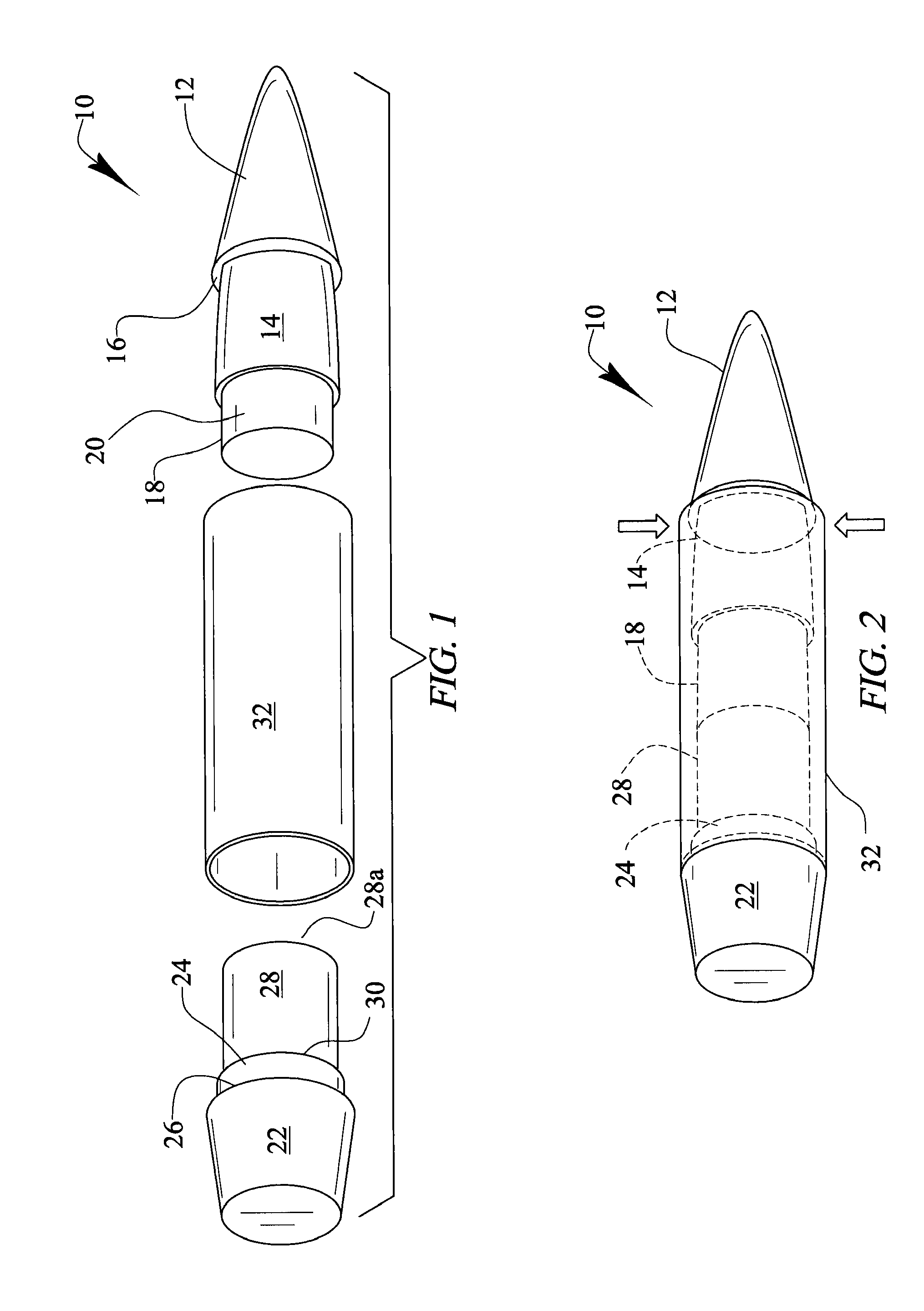
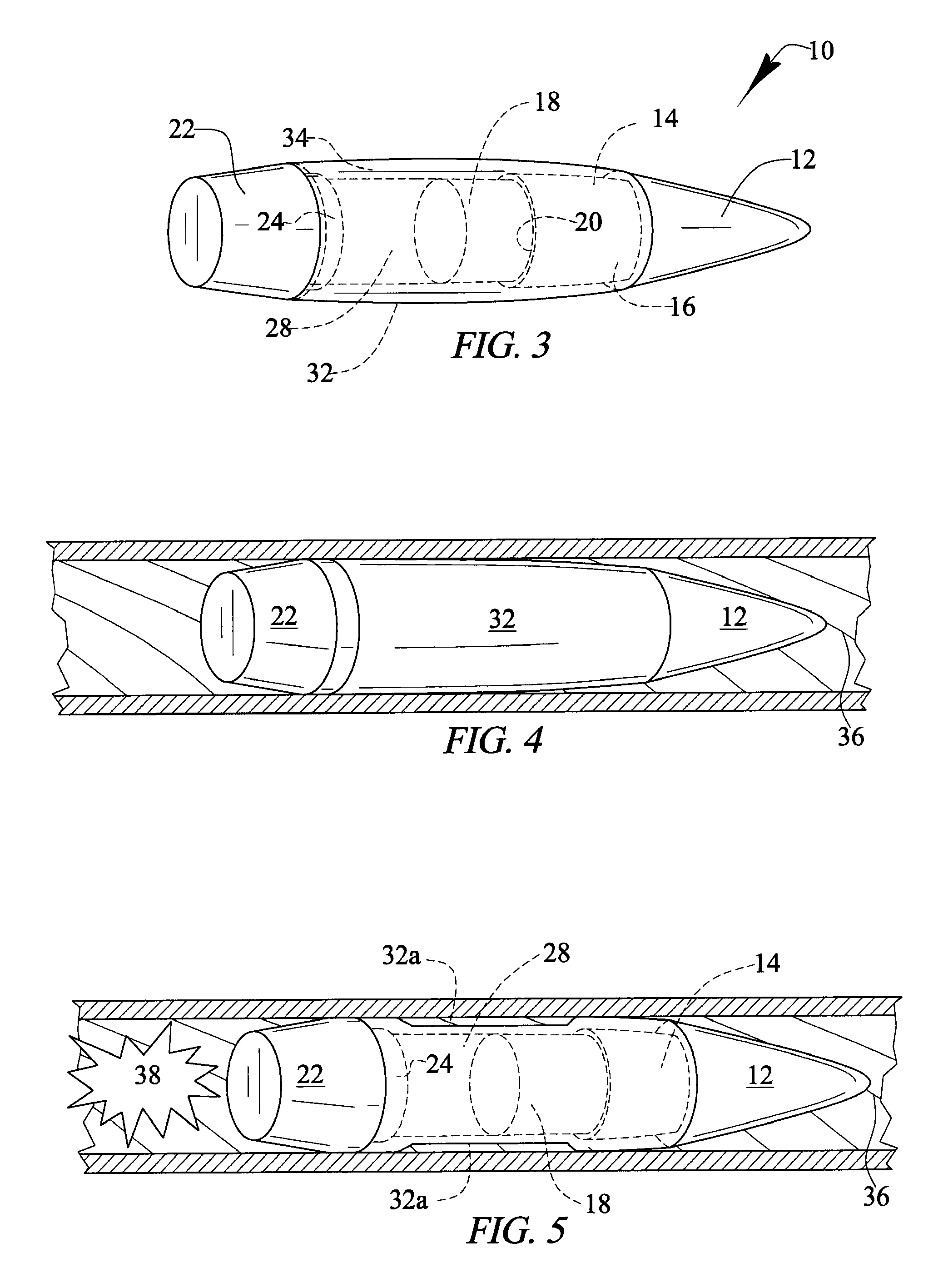
[0037]Referring now to FIG. 1, it will there be seen that an exploded perspective view of the novel projectile is denoted as a whole by the reference numeral 10.

[0038]Projectile 10 includes a leading part formed by nose cone or tip 12 having a generally ogive shape. Tip base 14 of solid cylindrical construction is integrally formed with tip 12 and has a reduced diameter so that first annular shoulder 16 is formed where the trailing end of tip 12 meets the leading end of tip base 14. Leading rod 18 is integrally formed with tip base 14 and has a reduced diameter so that second annular shoulder 20 is formed where the trailing end of tip base 14 meets the leading end of leading rod 18.

[0039]Projectile 10 further includes a trailing part formed by frusto-conical main base 22. Truncate base 24 of solid cylindrical construction is integrally formed with frusto-conical main base 22 and has a reduced diameter relative to the leading end of said main base so that third annular shoulder 26 is...


PUM


Abstract

A projectile includes a leading part formed by a tip, a tip base, and a leading rod. A trailing part includes a main base, a truncate base, and a trailing rod. A leading end of a cylindrical interface abuts an annular shoulder where the tip meets the tip base and a trailing end abuts an annular shoulder where the main base meets the truncate base. The tip base and the truncate base respectively support the leading and trailing ends of the cylindrical interface. A medial extent of the cylindrical interface is unsupported by the leading and trailing rods and is deformed radially inwardly by lands in a barrel when the projectile is fired. The leading and trailing ends of the cylindrical interface maintain contact with the lands and the medial extent does not, reducing friction between the projectile and the barrel without sacrificing spin of the projectile.

Description

CROSS-REFERENCE TO RELATED APPLICATIONS[0001]This application is a continuation-in-part of and claims priority to pending U.S. patent application Ser. No. 11 / 255,261, entitled: “Firearms Projectile,” filed Oct. 21, 2005 by the same inventor, which application is hereby incorporated by reference into this application. This application also claims priority to U.S. Provisional Patent Application No. 61 / 326,809, entitled “Reduced Friction Projectile,” filed Apr. 22, 2010 by the same inventor, which application is hereby incorporated by reference into this application.BACKGROUND OF THE INVENTION[0002]1. Field of the Invention[0003]This invention relates, generally, to the art of projectiles. More particularly, it relates to a projectile that is crimped at preselected locations along its length when fired.[0004]2. Description of the Prior Art[0005]Conventional projectiles engage the lands and grooves formed in a gun barrel along substantially the entire length of the projectile. About the...

Claims


Application Information

Patent Timeline
Patent Type & Authority Patents(United States)
IPC IPC(8): F42B14/02
CPCF42B14/02F42B1/028F42B10/00F42B10/02F42B12/82
Inventor MARX, PJ
Owner LIBERTY OPCO LLC
Why Eureka
Try Eureka