Electrogasdynamic method for generation electrical energy

Inactive Publication Date: 2005-01-11
LUCHINSKIY ALEXANDER +2
View PDF28 Cites 26 Cited by
  • Summary
  • Abstract
  • Description
  • Claims
  • Application Information

AI Technical Summary

Benefits of technology

The object of the process of the presently claimed invention is to increase the power and the effici

Problems solved by technology

The power of these devices is limited on the one hand by the maximum allowable surface density of charges on a conveyor, the carrier of the charge, on the one hand, and by the

Method used


Image

  • Electrogasdynamic method for generation electrical energy
  • Electrogasdynamic method for generation electrical energy
  • Electrogasdynamic method for generation electrical energy

Examples


Embodiment Construction

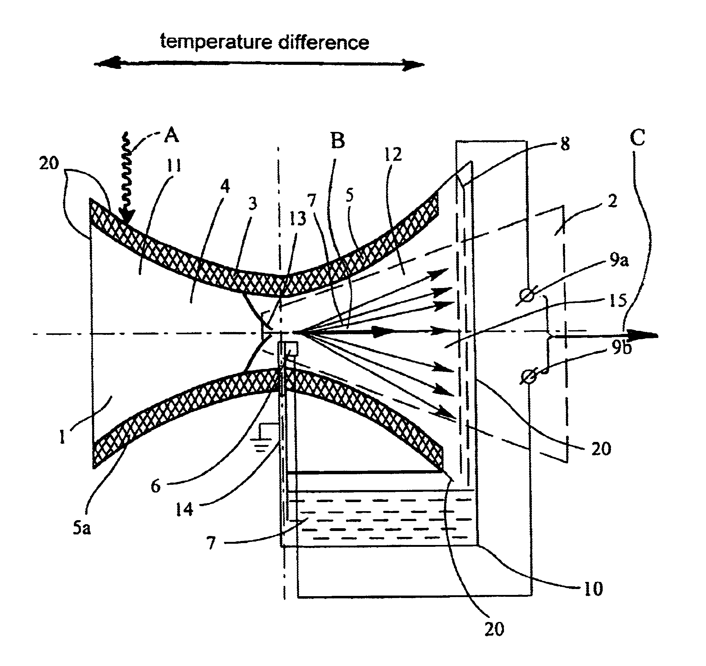
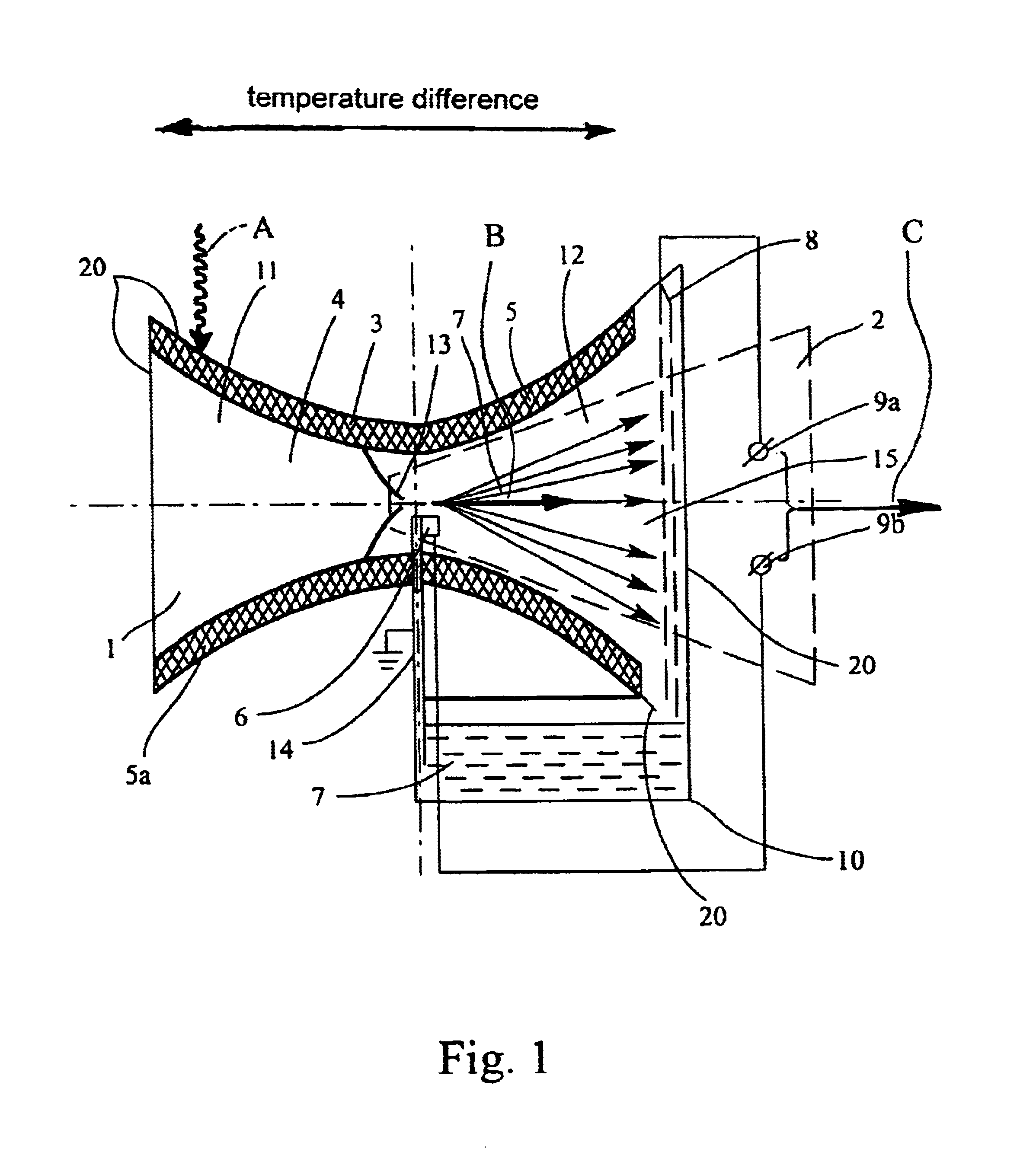
All types of devices for enablement of the process of the present invention contain a heat pipe 1 and a generator 2. The heat pipe has a working medium in the liquid phase, i.e., the working liquid 3 which is vaporized to the gaseous phase, i.e., the working gas 4, and a capillary insert 5. The generator 2 contains the solid working medium 6 of the generator 2, the liquid working medium 7 of the generator 2, the pick-up electrode (grid) 8 for charge pick-up, the external electrodes 9a and 9b and the loop 10 for return of the liquid working medium 7.

When a temperature gradient builds up between the vaporizer 11 and the condenser 12 of the heat pipe 1, the working liquid 3 of the heat pipe, vaporizes in the vaporizer on its capillary structure 5a. At the same time the working gas 4 of the heat pipe 1 condenses on the capillary structure 5a of the capillary insert 5 of the condenser 12 of the heat pipe 1. The working liquid 3 travels via the capillary insert 5 out of the condenser 12 b...


PUM


Abstract

A process is provided for producing electrical energy from thermal energy in which charges are separated between two working media triboelectrically or electrostatically, the charges are moved away from one another by displacement of the working media under the action of gas flow forces. In the process, these gas flow forces perform work against the Coulomb forces, and the charges are routed onto electrodes. The process steps are carried out within the inside volume of a heat pipe, with charge separation and charge displacement taking place using the directed gas flow within the heat pipe. The gas flow entrains a liquid medium and routes it past the other working medium for charge separation and displacement. An application of the present invention is in the use of solar energy.

Description

STATEMENT REGARDING FEDERALLY SPONSORED RESEARCH OR DEVELOPMENTNot ApplicableREFERENCE TO A “MICROFICHE APPENDIX”Not ApplicableBACKGROUND OF THE INVENTION(1) Field of the InventionThe present invention relates to a process for generating voltages by mechanical displacement of electrical charges. More particularly, the charges between two working media are separated by triboelectrification or by induced static electricity, one of the two media being electrically connected to an electrode and the second working medium being transferred to another electrode on which the charge is picked up.(2) Description of Related ArtDevices used in the process of the present invention; see DE 23 36 487 A1 and European Patent Application 0229 843 A1 for a description of a prior art electrostatic generator.A process is known for producing electrical energy by friction of certain stiff dielectric surfaces consisting of different materials against one another, and it is accomplished in a compact device;...

Claims


Application Information

Patent Timeline
IPC IPC(8): H02N3/00
CPCH02N3/00F28D15/02
Inventor LUCHINSKIY, ALEXANDERWERTH, GUNTHERSHIFRIN, YAKOV
Owner LUCHINSKIY ALEXANDER
Why Eureka
Try Eureka