A method for modeling a compressor speed

a compressor and speed modeling technology, applied in the direction of machines/engines, process and machine control, instruments, etc., can solve the problems of high cycle fatigue, large changes in material structure, and low cycle fatigue of compressors, so as to improve the accuracy of speed modeling, and improve the effect of accuracy

Active Publication Date: 2018-03-15
VOLVO LASTVAGNAR AB
View PDF2 Cites 0 Cited by
  • Summary
  • Abstract
  • Description
  • Claims
  • Application Information

AI Technical Summary

Benefits of technology

[0016]In an embodiment the step of estimating the temperature downstream the compressor is performed by measuring the temperature in an air inlet manifold, and correcting this temperature by a factor corresponding to the temperature loss across an associated cooler. Hence, accuracy of the speed modeling method is further improved.
[0017]In an embodiment the method further comprises the step of determining the pressure ratio across the compressor. Further, the step of calculating the compressor speed value is performed by calculating the compressor speed value as a function of the pressure ratio. By including the pressure ratio across the compressor as input for the compressor speed modeling method, accuracy may be further improved.
[0018]In an embodiment the step of determining the pressure ratio across the compressor is performed by determining if the ambient pressure is below a preset ambient pressure corresponding to high altitude conditions, and if so, setting the ambient pressure as the preset ambient pressure, and dividing the boost pressure with the ambient pressure. In this embodiment, high altitude conditions are also considered. This is highly beneficial for increasing the accuracy of the speed modeling. As there is otherwise a risk of overestimating the compressor speed, this will avoid unnecessary torque derate at higher alt

Problems solved by technology

In particular, wear of the compressor is typically categorized by low cycle fatigue and high cycle fatigue.
Low cycle fatigue corresponds to relatively small fluctuations in compressor speed, while high cycle fatigue corresponds to relatively rapid (and large) changes in compressor speed.
Fatigue will eventua

Method used


Image

  • A method for modeling a compressor speed
  • A method for modeling a compressor speed
  • A method for modeling a compressor speed

Examples


Embodiment Construction

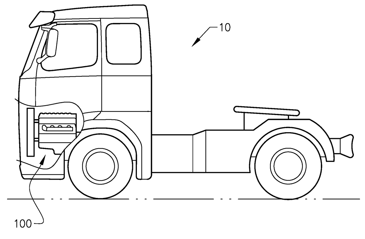
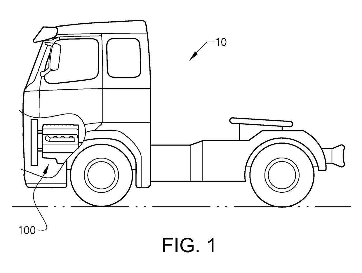
[0046]Starting with FIG. 1 a vehicle 10 is shown. The vehicle 10, which is illustrated as a truck, has an internal combustion engine 100 for driving the vehicle 10. As will be further explained below the internal combustion engine 100 of the vehicle 10 is provided with a turbocharger 130 and a controller 200. The vehicle 10 may have additional propulsion units, such as electric drives etc. as long as it has at least one engine providing a flow of exhaust gases interacting with the turbocharger unit 130. Hence the vehicle 10 is not exclusively a truck but may also represent various vehicles such as buses, constructional equipment, etc.

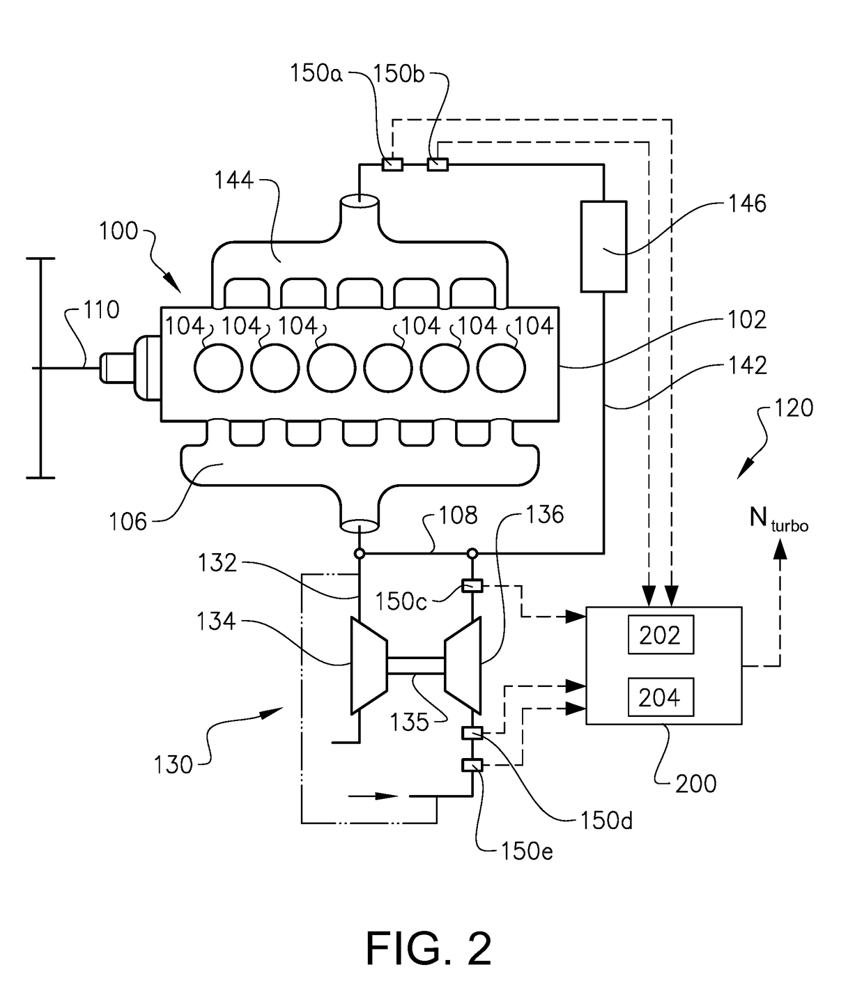
[0047]InFIG. 2 an example of an internal combustion engine 100 is shown. The internal combustion engine 100 includes a cylinder block 102 being provided with a plurality of cylinders 104 operated to combust fuel, such as diesel or gasoline, whereby the motion of pistons reciprocating in the cylinders 104 is transmitted to a rotation movement of a crank ...


PUM


Abstract

A method is provided for modeling the compressor speed of a turbocharger, and includes determining the temperature difference across the compressor, determining the mass flow through the compressor, and calculating a compressor speed value as a function of the temperature difference across the compressor and the mass flow.

Description

BACKGROUND AND SUMMARY[0001]The invention relates to a method for modeling the speed of a compressor, in particular for a turbocharger.[0002]The invention can be applied in heavy-duty vehicles, such as trucks, buses and construction equipment. Although the invention will be described with respect to a truck, the invention is not restricted to this particular vehicle, but may also be used in other applications utilizing turbocharger units such as aero or marine systems.[0003]A turbocharger is a vehicle component used together with an associated internal combustion engine, typically a diesel engine. The turbocharger is configured to recover a part of the energy of the exhaust gas and to use that energy to compress intake air flowing into the combustion chamber of the internal combustion engine. Turbochargers are commonly provided for increasing the efficiency and power of the internal combustion engine.[0004]A turbocharger has three main components; a turbine for converting energy of ...

Claims


Application Information

Patent Timeline
IPC IPC(8): F01D17/06G05B17/02F02B39/16F02B37/18
CPCF01D17/06G05B17/02F02B39/16F02B37/18F05D2220/40F02B2039/168F05D2270/708Y02T10/12
Inventor MURIC, KENANWASSEN, HENRIK
Owner VOLVO LASTVAGNAR AB
Why Eureka
Try Eureka