Hydrogen Jet Propulsion System

a propulsion system and hydrogen jet technology, applied in marine propulsion, boat construction, applications, etc., can solve the problems of limited performance of systems, low power consumption, and low power supply of watercraft electric motors, and achieve the effect of increasing the power and efficiency of the propulsion tub

Active Publication Date: 2014-11-06
BHI GLOBAL
View PDF6 Cites 0 Cited by
  • Summary
  • Abstract
  • Description
  • Claims
  • Application Information

AI Technical Summary

Benefits of technology

[0014]The propulsion tube can have rifling grooves or ridges across the inside surface of the tube to increase power and efficiency of the pr...

Problems solved by technology

Electric motors for watercraft are limited by battery supply, weight and power consumption.
Current battery technologies and recharging technologies do not support lo...

Method used


Image

  • Hydrogen Jet Propulsion System
  • Hydrogen Jet Propulsion System
  • Hydrogen Jet Propulsion System

Examples


Embodiment Construction

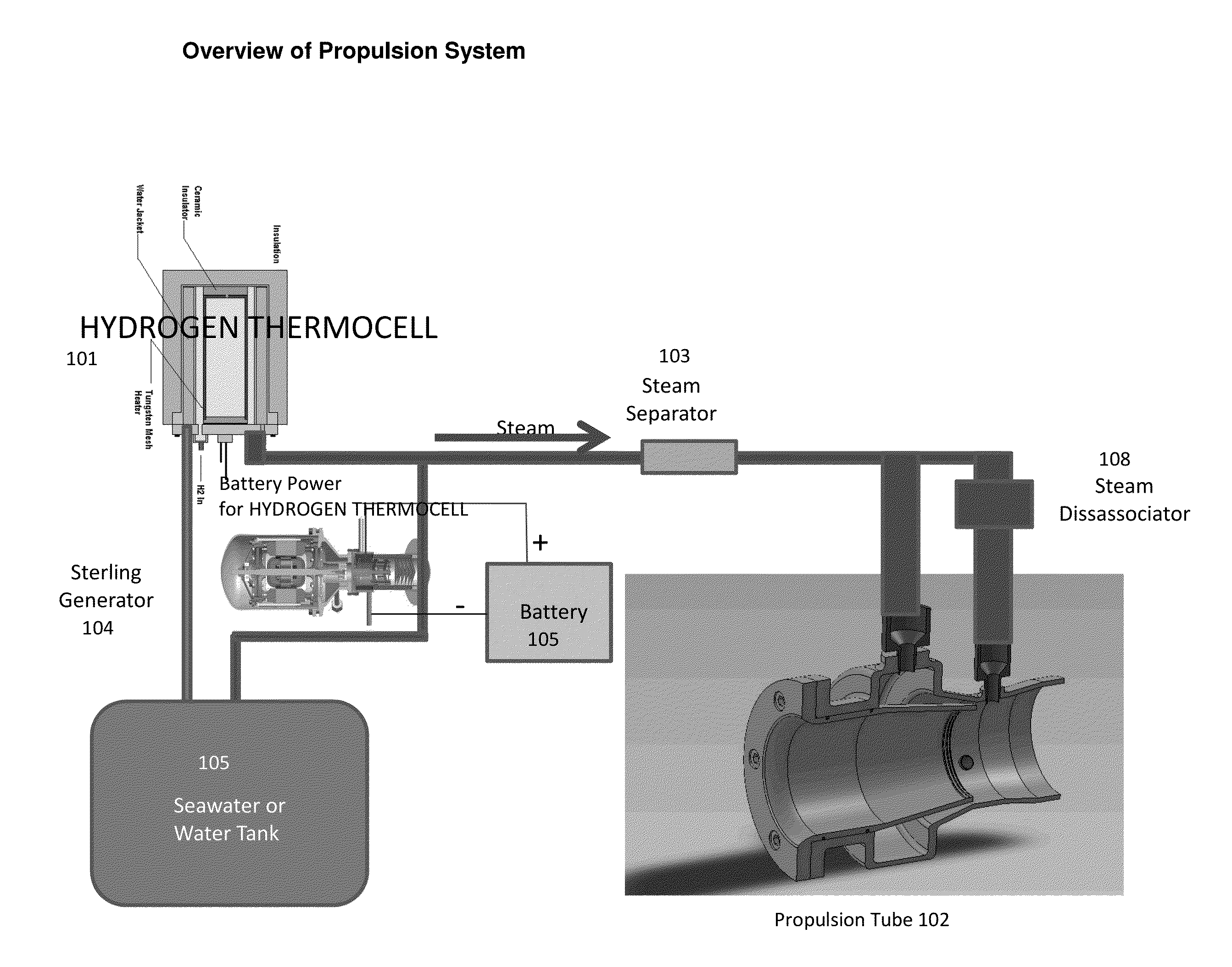
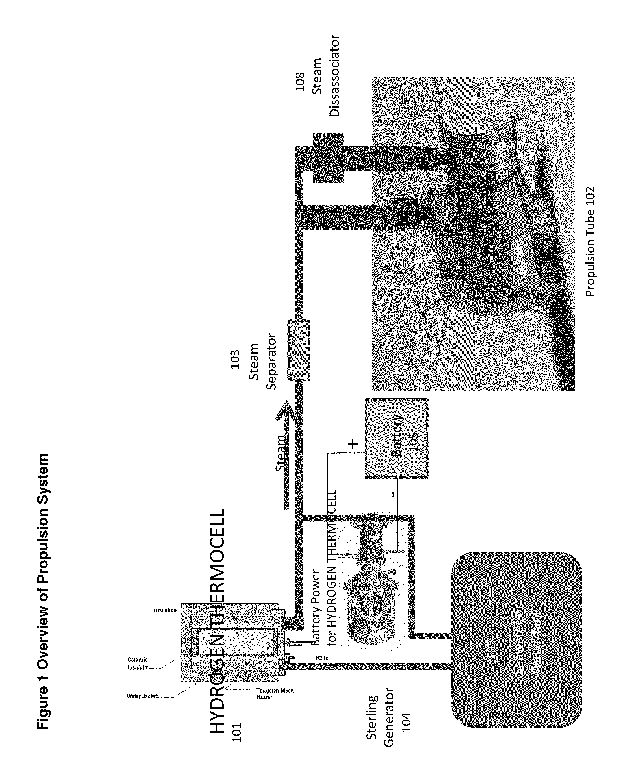
[0029]In FIG. 1 we present an overview of propulsion system. The low energy reactor (101) provides the heat energy in the form of steam to drive a generator (104) to supply electricity to the system and the propulsion tube (102). The steam separator (103) is used to separate hydrogen and oxygen in the steam and uses high temperature electrolysis to accomplish this. The steam separator (high temperature electrolysis) may use electrical current to assist in the electrolysis process. The steam dissassociator (108) uses a high temperature grid to break the hydrogen and or oxygen atoms apart to form atomic hydrogen and or atomic oxygen. The batter (105) is used to start the system and is recharged from the generator (104). Seawater, freshwater or water from a storage tank is used (105) to supply the low energy reactor (101).

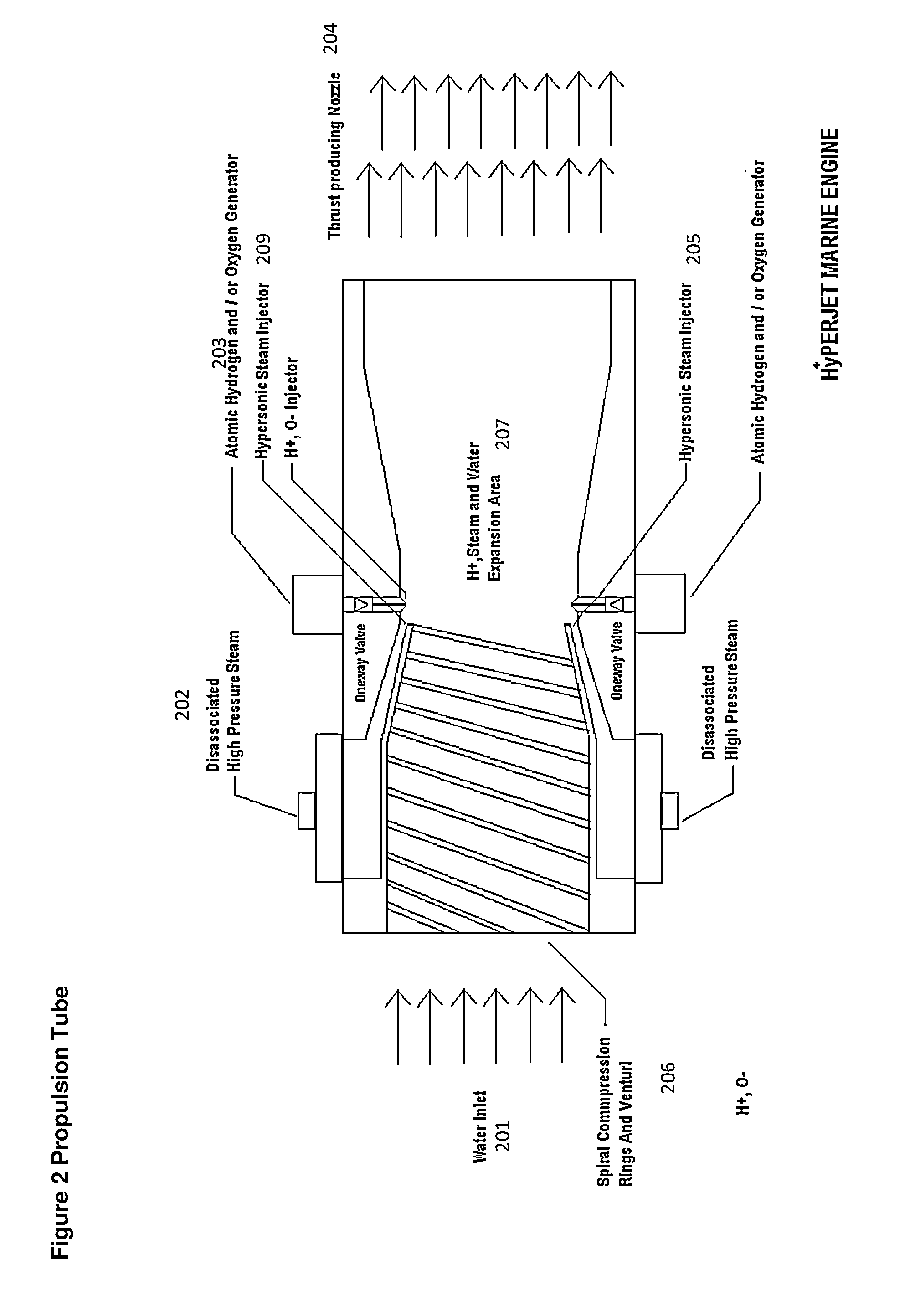
[0030]In FIG. 2 we illustrate the propulsion tube where steam or separated steam in to hydrogen and or oxygen or a combination of steam and or hydrogen and oxygen (20...


PUM


Abstract

A propulsion system for watercraft that uses steam generated from low energy reactor to enable long range high power propulsion. The system preferably uses steam generated from a low energy reactor to provide on-demand steam generated without external power.

Description

CROSS-REFERENCE TO RELATED APPLICATIONS[0001]This application claims priority from prior provisional application 61 / 851,809 filed on Mar. 13, 2013. This application claims priority from prior provisional application 61 / 855 / 140 filed on May 9, 2013. The entire collective teachings thereof being herein incorporated by reference.FIELD OF THE INVENTION[0002]A hydrogen based propulsion system for watercraft that uses a disassociated hydrogen to create a water jet affect to enable long range high power propulsion. The system preferably uses water converted into atomic hydrogen from a heat source to provide on-demand fuel generation for the propulsion system.DESCRIPTION OF RELATED ART[0003]There is a great need for a watercraft propulsion system that does not need fossil fuels for combustion engines or stored fuels such as hydrogen an or propane gas to power a propulsion system. Electric motors for watercraft are limited by battery supply, weight and power consumption. Electric boats, othe...

Claims


Application Information

Patent Timeline
IPC IPC(8): B63H1/30B63H20/00F24V30/00
CPCB63H1/30B63H20/00B63H11/16F24V30/00
Inventor FRANK, DAVID LORON
Owner BHI GLOBAL
Why Eureka
Try Eureka