

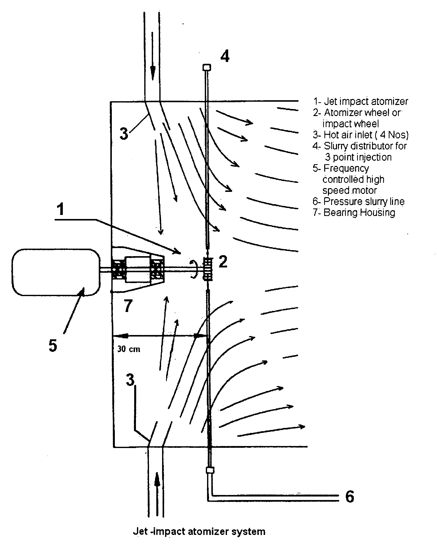
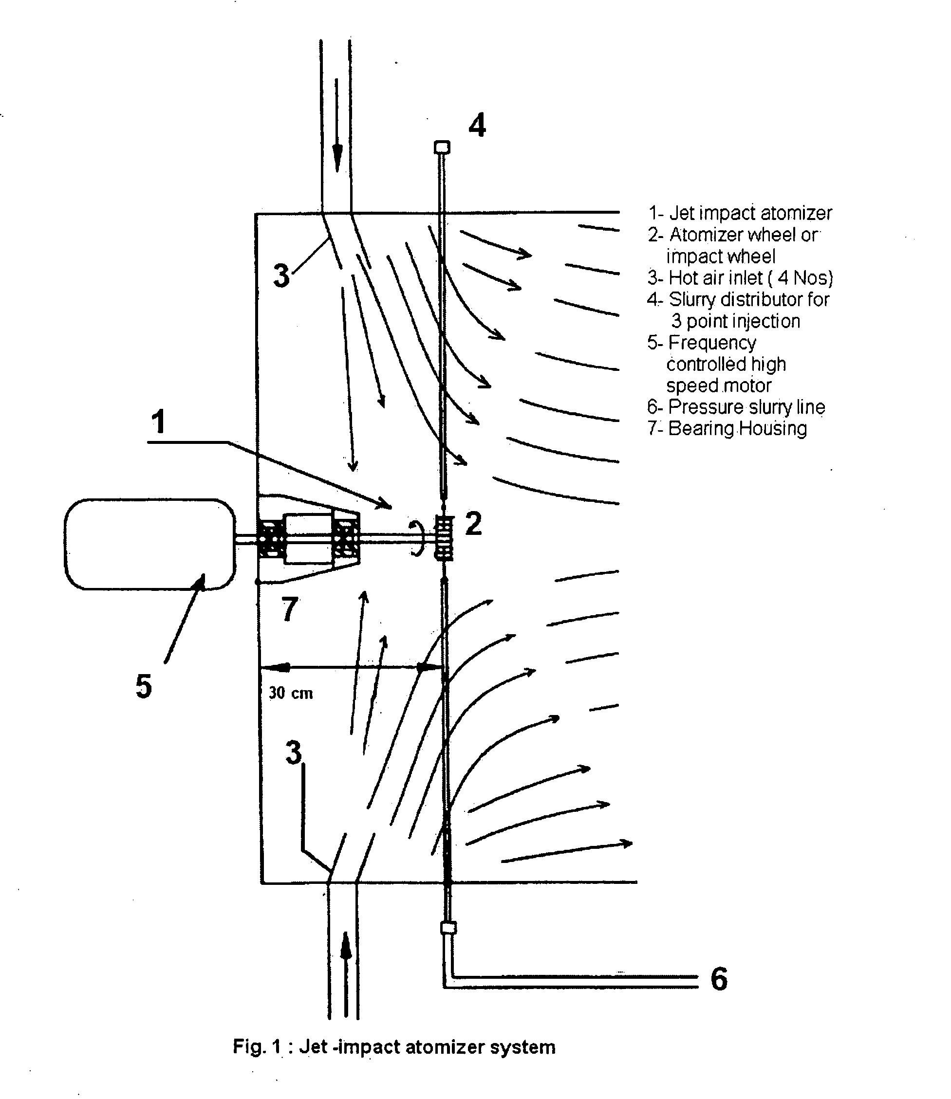
Jet-wheel impact atomizer for spray drying and a process for the preparation of finely dispersed spray of slurry/liquid
a technology of slurry/liquid spray and atomizer, which is applied in the direction of liquid degasification, separation processes, lighting and heating apparatus, etc., can solve the problems of high maintenance cost of high-speed rotating parts, high nozzle wear, and high pressur
- Summary
- Abstract
- Description
- Claims
- Application Information
AI Technical Summary
Benefits of technology
Problems solved by technology
Method used
Image

Examples
example 1
[0105] 40 wt % alumina-water slurry is prepared for spray drying as per the following composition:
Alumina powder:4291.78 gParticle size:d50 = 0.3-0.6 μmd90 = 1.5 μmPoly vinyl alcohol (PVA): 55.79 gAmmonium Poly Acrylate (APA) 85.83 gEthylene glycol (EG): 6.693 gWater:6289.42 gViscosity of the slurry: 16.8 cP
[0106] The slurry is prepared in a container by homogenising the mixture with an electrically driven stirrer. It is stirred for 1 hour and then poured in to the slurry tank and is allowed to be constantly agitated there by a stirrer. Electrical power is switched on at the control console and the inlet and outlet air flows of the drying chamber are made on. The heater is then switched on to heat the inlet air by electrical means. The temperature of the inlet air and outlet air are monitored through thermocouples. The drying chamber pressure was monitored by a water manometer. After about 30 minutes, when the temperature of the outlet air shows around 70° C., the atomizer wheel ...
example 2
[0109] As per the following composition, 30% slurry is prepared for spray drying:
Alumina powder: 2543 g,Particle size:d50 = 0.3-0.6 μmd90 =1.5 μmPoly vinyl alcohol (PVA):33.950 gAmmonium Poly Acrylate (APA):50.851 gEthylene glycol (EG): 3.966 gWater: 5753 gViscosity of slurry: 13.15 cP
[0110] The experimental procedure employed in Example 1 are followed to produce the powder. Process conditions maintained in this case are:
[0111] Slurry pressure: 1-2 bar
[0112] Drying air temperature: Inlet temperature 100° C., Outlet temperature 415° C.
[0113] RPM of atomizer wheel: 13,745
[0114] Drying chamber pressure: 1.04 bar
[0115] Time required to spray the slurry: 12-15 min.
[0116] Hot air flow rate: 50 m3 / hour.
[0117] Diameter of wheel used: 100 mm
[0118] Nozzle orifice diameter: 0.6 mm
[0119] The powder thus produced has been evaluated and show the following characteristic properties:
[0120] Mass yield: 80.7%.
[0121] Particle / grain size: 37.5-105 μm (75.7%).
[0122] Morphology of the gra...
example 3
[0130] 30% slurry of the composition in Example 2 is sprayed under similar process conditions of the said example except change in wheel rpm and diameter. The rpm of the atomizer is maintained at 13,745 and the wheel diameter is 75 mm.
[0131] The powder thus produced has been evaluated and shows the following characteristic properties:
[0132] Mass yield: 80.1%.
[0133] Particle / grain size: 37.5-105 μm (73.34%).
[0134] Morphology of the grains: spheroidal with sphericity 0.94.
[0135] Density of the powder:
[0136] Bulk density: 0.804 g / cm3, Tap density: 0.893 g / cm3, Fill density: 20.45%, Moisture level: 1.26 wt %
[0137] Porosity in grains: 37%.
[0138] The crystallographic phase of the powder determined by XRD is found to occur as α-alumina (corundum). The phase of the feed solid in slurry and the spray dried solid are observed to be the same.
PUM
| Property | Measurement | Unit |
|---|---|---|
| temperature | aaaaa | aaaaa |
| temperature | aaaaa | aaaaa |
| pressure | aaaaa | aaaaa |
Abstract
Description
Claims
Application Information