
Methods and Devices for Facile Fabrication of Nanoparticles and Their Applications

a nanoparticle and fabrication method technology, applied in the direction of measuring apparatus housings, crystal growth processes, mixers, etc., can solve the problems of specialized equipment, dangerous reaction conditions, and often hazardous reagents, and achieve the effect of reducing some drag and improving mixing efficiency

Inactive Publication Date: 2008-04-24
VIRTANEN JORMA ANTERO +2
View PDF4 Cites 27 Cited by
  • Summary
  • Abstract
  • Description
  • Claims
  • Application Information

AI Technical Summary

Benefits of technology

[0014] It is a further object of the present invention to increase the interaction of the reactants by increasing their kinetic energy by ultrasonic vibration. Ultrasonic vibration is most efficiently generated by a piezo crystal that may be outside the fluidic system and by physically connected to it by solid or liquid material, or it may be inside the fluidic system, or it may be integrated with the walls of the fluidic system.
[0016] Another purpose of the present invention to provide large arrays of microfluidic continuously operating chips so that industrial scale production is possible.
[0020] In one embodiment of the current invention the quality of nanoparticles can be continuously monitored by integrating optical inspection methods, such as UV / Vis, and fluorescence spectroscopy with the microfluidic system of this invention. The inspection system has been connected via a microprocessor to the pumping mechanism so that the reagent addition can be continuously optimized for the best quality.

Problems solved by technology

The drawback is that the reagents are often hazardous, and the reaction conditions are potentially dangerous with these reagents in low boiling solvents and at high temperatures.
Flame deposition, and electrospray require specialized equipment, which have fairly limited throughput.
Sol-gel method gives NPs in a solid matrix, and its use is limited into the cases, when NPs can be used in that form.
Most of the methods are limited to one or two types of NPs.
The problem with reverse micelle method is that it often gives large size distribution.
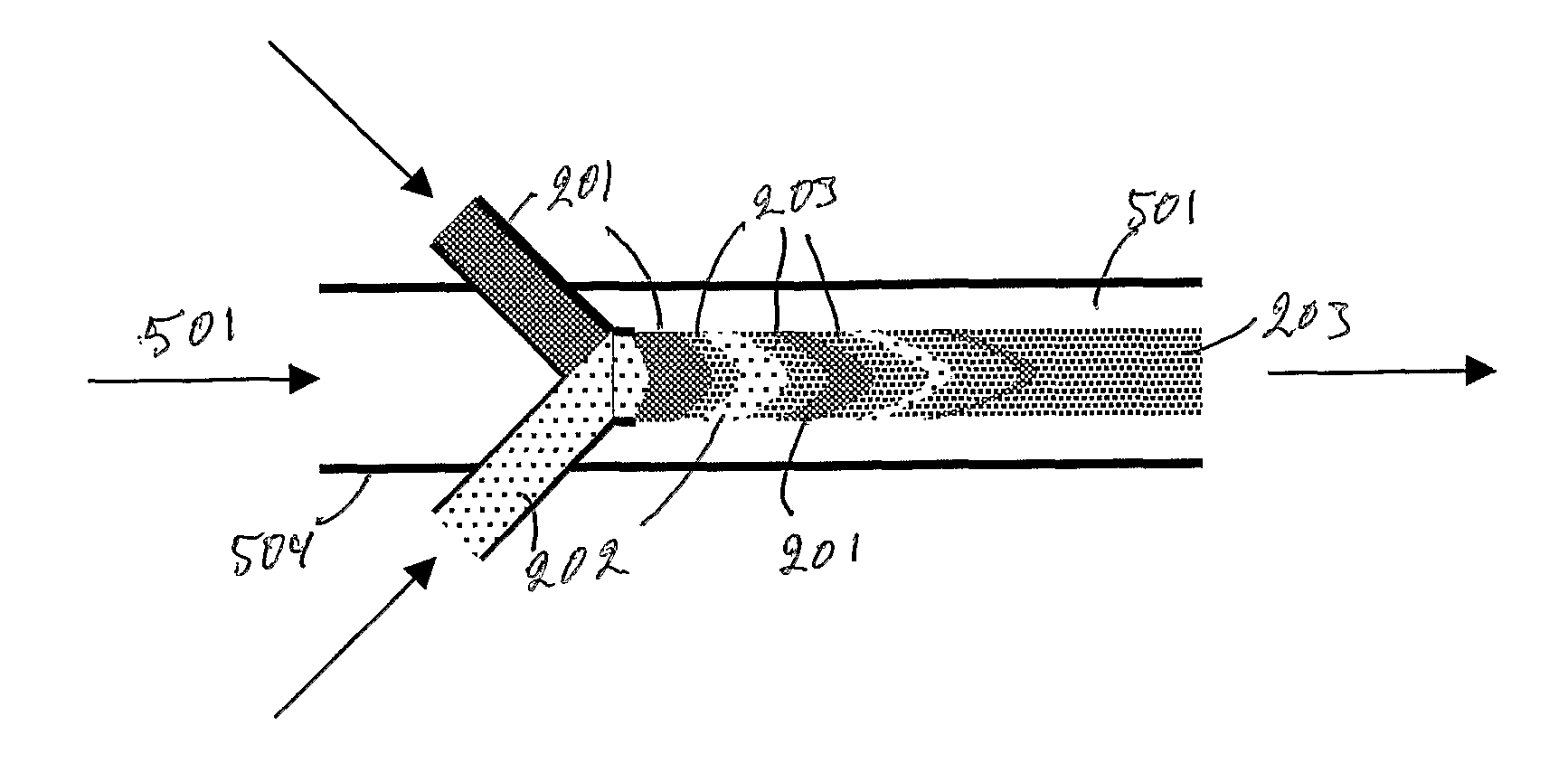
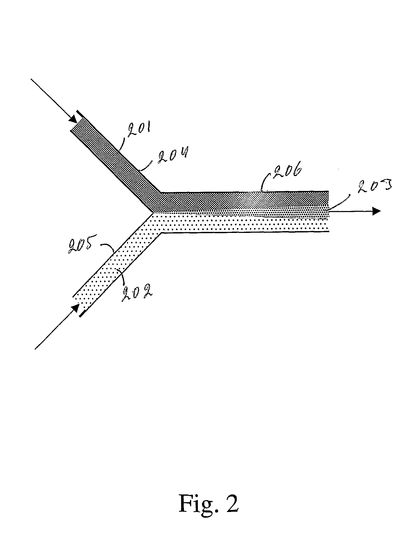
Mixing of components in nano- and microfluidic systems is difficult, because the flow is laminar (FIG. 2).

Method used


Image

  • Methods and Devices for Facile Fabrication of Nanoparticles and Their Applications
  • Methods and Devices for Facile Fabrication of Nanoparticles and Their Applications
  • Methods and Devices for Facile Fabrication of Nanoparticles and Their Applications

Examples


example 1

Fabrication of Cadmium Sulfide

[0110] First, the following solution were made: 4.44 g of sodium bis(2-ethyl hexyl)sulfosuccinate (AOT) in iso-octane in a 100 ml volumetric flask (0.1 M), 332 mg of sodium sulfide in 10 ml of water in a 10 ml volumetric flask (0.4 M), and 1146 mg of cadmium nitrate in water in a 10 ml volumetric flask (0.4 M). Two different preparations of cadmium sulfide nanoparticles were made from these stock solutions. [0111] A. Two 10 ml aliquots of AOT solution were measured into two test tubes. Into one of these was added 80 μl of cadmium nitrate solution, and into the other 80 μl sodium sulfide solution with good mixing. The solutions were allowed to stabilize for 2 hours. After the equilibration the solutions were put into a microfluidic reactor, and using a syringe pump, the two components were pumped in 0.2 μl increments as alternating pulses via 3-way connector into a Teflon tube (2 mm diameter, 1.5 m long). The pumping speed was 0.4 ml / min for both soluti...

example 2

[0114] The fabrication was performed exactly as in Example 1, but the receiving vial did not contain any capping reagent. Instead the product solution (20 ml) as such, and 4 mg of niobium isopropoxide in 5 ml of isooctane / ethanol 4:1 were pumped into the microfluidic reactor. In each pumping cycle 0.8 μl of CdS nanoparticle solution, and 0.2 μl of niobium ethoxide solution were pumped. The product solution that contained niobium oxide coated CdS nanoparticles was put once more in the starting vial, and this time the other component was a reverse micellar solution made of adding 40 μl of poly-L-lysine (PLL, 2 mg) water solution into 10 ml of AOT base solution. In one cycle 0.5 μl of nanoparticle solution, and 0.2 μl of PLL solution were pumped in the mixing capillary. Three layer nanoparticles were isolated by adding 10 ml of water, separating the organic layer, and dialyzing the water phase three times against 200 ml of water. These CdS core nanoparticles can be attached with standa...

example 3

[0115] Janus(6v8) (FIG. 12) was dissolved into ethanol, concentration was 5 mg / ml. Merocyanine 540 was added into the solution to the final concentration of 0.5 mol % of janus(6v8). This solution was injected into ten fold excess of water in 0.1 μl portions. The liposomes were dialyzed in line first against 10% ethanol in water and then against pure water. Similarly, liposomes were prepared of all janus molecules in FIG. 12 with and without merocyanine 540. Especially janus(6v8) liposomes have sharp phase transition at 39° C. that can be detected with differential scanning calorimeter. The fluorescence of merocyanine 540 increased at the same temperature, which indicates that merocyanine 540 penetrates into the alkyl chain layer. Thus, these liposomes are ideal temperature activated drug carriers.


PUM

PropertyMeasurementUnit
thicknessaaaaaaaaaa
thicknessaaaaaaaaaa
frequencyaaaaaaaaaa

Abstract

The invention provides devices and methods to fabricate nanoparticles by reverse micelle method. The method allows to fabricate a myriad of high quality nanoparticles in a repeatable way. These nanoparticles include multilayered spherical and rod like particles that may have inorganic, organic, polymeric, biological layers. The invention further provides methods to optimize the quality of the nanoparticles.

Description

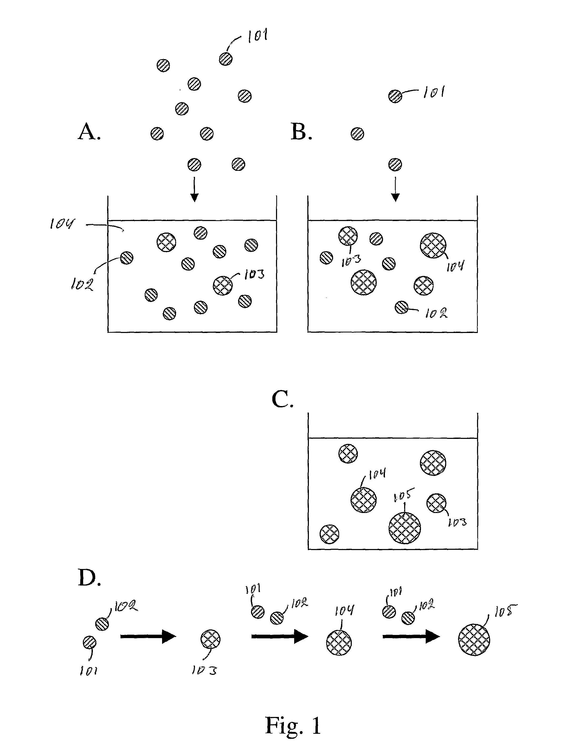
CROSS REFERENCE TO RELATED APPLICATIONS [0001] This application claims priority from Finnish Application Serial No. 20041435, filed Nov. 9, 2004, and Finnish Application Serial No. 20041656, filed Dec. 23, 2004, and Finnish Application Serial No. 20050101, filed Jan. 31, 2004, and Finnish Application Serial No. 20050406, filed Apr. 21, 2004, and Finnish Application Serial No. 20050429, filed Apr. 26, 2004. BACKGROUND [0002] 1. Field of the Invention [0003] This invention provides devices, methods for the fabrication of nanoparticles and applications for these nanoparticles. The fabrication method is based on accurate control of the microfluidics, and the chemical composition of the reaction mixture. This is made possible by a in-line monitoring system and microprocessor control of the various physical and chemical parameters of the system. [0004] 2. Prior Art and Overall Description [0005] Nanoparticles (NPs) are widely used in various applications, which include luminescent particl...

Claims


Application Information

Patent Timeline
Patent Type & Authority Applications(United States)
IPC IPC(8): A61K49/00C09K11/02A61L2/28B01F31/80
CPCB01F13/0062C30B7/00B01F15/0241B01J19/0093B01J2219/00788B01J2219/0086B01J2219/00864B01J2219/00873B01J2219/00889B01J2219/0093B01J2219/00932B01J2219/00941B01J2219/00972B01J2219/00975B01J2219/00986B01L3/5027B82Y5/00B82Y10/00B82Y20/00B82Y30/00G01N2015/0038B01F15/0203B01F33/3011B01F35/712B01F35/717551
Inventor VIRTANEN, JORMA ANTEROKEINANEN, PASITILLI, MIKKO
Owner VIRTANEN JORMA ANTERO
Learn More