Rotor unit, bearing mechanism, motor, and data storage disk drive device

a technology of bearing mechanism and drive device, which is applied in the direction of magnetic circuit rotating parts, magnetic circuit shape/form/construction, instruments, etc., can solve the problems of deformation of shaft, deformation of shaft, and deformation of shaft, so as to reduce the friction between shaft and bushing during interference fitting

Inactive Publication Date: 2007-10-11
NIPPON DENSAN CORP
View PDF23 Cites 17 Cited by
  • Summary
  • Abstract
  • Description
  • Claims
  • Application Information

AI Technical Summary

Benefits of technology

[0008]Through the configuration mentioned above, friction between the shaft and the bushing during the interference-fitting is reduced, and the shaft and the bushing are firmly fixed to each other while the force of interference-fitting the shaft into the bushing is preferably adjusted.

Problems solved by technology

By making the portion of the shaft that is interference-fitted to the rotor hub axially longer, excessive load is applied to the shaft, deforming the shaft upon interference-fitting thereof.
The deformed shaft may degrade the perpendicularity of the rotor hub, and the lubricating oil used in a bearing mechanism of the motor may leak to the outside of the motor along an outer circumferential surface of the deformed shaft.

Method used


Image

  • Rotor unit, bearing mechanism, motor, and data storage disk drive device
  • Rotor unit, bearing mechanism, motor, and data storage disk drive device
  • Rotor unit, bearing mechanism, motor, and data storage disk drive device

Examples


Embodiment Construction

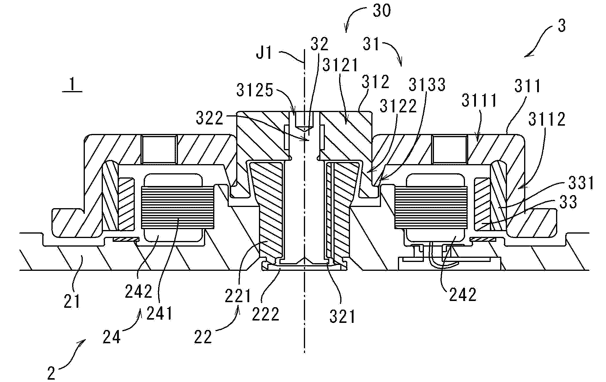
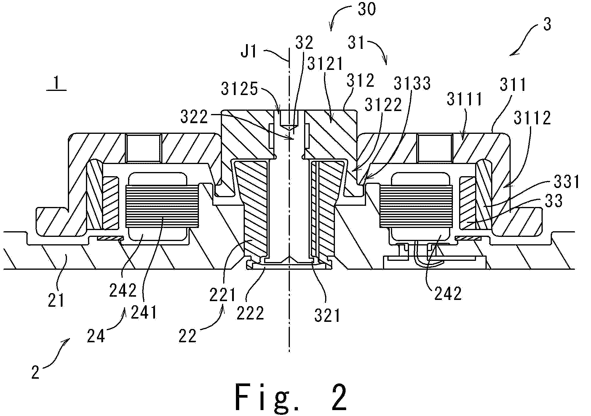
[0019]Referring to FIGS. 1 through 7, preferred embodiments of the present invention will be described in detail. It should be noted that in the explanation of preferred embodiments of the present invention, when positional relationships among and orientations of the different components are described as being up / down, left / right, or the like ultimately positional relationships and orientations that are in the drawings are indicated; positional relationships among and orientations of the components once having been assembled into an actual device are not indicated. In the following description, an axial direction indicates a longitudinal direction of a rotation axis, and a radial direction indicates a direction that is perpendicular or substantially perpendicular to the rotational, or center, axis of the motor.

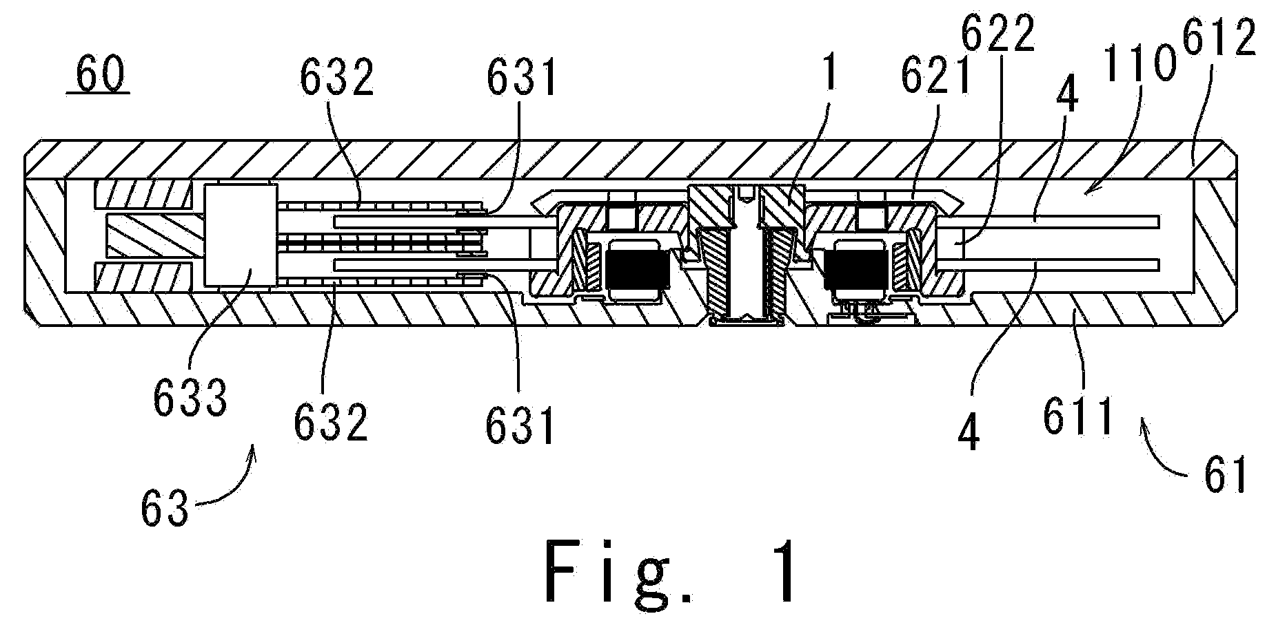
[0020]With reference to FIG. 1, the internal configuration of a storage disk drive 60, according to a first preferred embodiment of the present invention, including an electri...


PUM

PropertyMeasurementUnit
angleaaaaaaaaaa
angleaaaaaaaaaa
angleaaaaaaaaaa

Abstract

In bearing mechanism for a motor spinning a storage disk about a center axis, an interference-fit portion of a shaft is interference-fitted into a through hole of a bushing from an axial lower side thereof such that the shaft is fixed to a rotor hub. The interference-fit portion of the shaft is defined with an upper section, a lower section, and a concave portion. When the shaft is interference-fitted into the bushing, the upper and lower sections engage with the bushing, and the concave portion radially faces an inner surface of the bushing with a gap defined therebetween.

Description

BACKGROUND OF THE INVENTION[0001]1. Field of the Invention[0002]The present invention generally relates to a rotor unit to which a storage disk is fixed, a motor including the rotor unit, and a storage disk drive including the motor.[0003]2. Description of the Related Art[0004]A storage disk drive such as a hard disk conventionally includes a spindle motor for rotationally driving the storage disk(s) arranged on a rotor hub of the spindle motor (such spindle motors will be simply referred to as a motors hereinafter). One bearing mechanism that has been used in the motor is a fluid dynamic-pressure bearing mechanism (hereinafter simply referred to as FDB), in which the hydrodynamic pressure induced in lubricating oil retained between a stator unit (e.g., a sleeve unit fixed to a base plate of the motor) and a rotor unit (e.g., a shaft fixed to the rotor hub and inserted into the sleeve) is used for rotatably supporting the rotor unit.[0005]Generally, in the manufacture of the motor, ...

Claims


Application Information

Patent Timeline
Patent Type & Authority Applications(United States)
IPC IPC(8): H02K5/16G11B17/02F16C32/06
CPCG11B17/028H02K1/30F16C2370/12H02K7/085H02K15/03H02K5/1675
Inventor FUKUSHIMA, KAZUHIKO
Owner NIPPON DENSAN CORP
Why Eureka
Try Eureka