Electrostatic levitation furnance

a technology of electric levitation furnace and electric levitation chamber, which is applied in the direction of furnaces, lighting and heating apparatus, electric/magnetic/electromagnetic heating, etc., can solve the problems of improper use, difficult access to sample samples, and difficulty in increasing the number of access and distribution apparatuses

Inactive Publication Date: 2005-02-03
IHI AEROSPACE CO LTD
View PDF4 Cites 10 Cited by
  • Summary
  • Abstract
  • Description
  • Claims
  • Application Information

AI Technical Summary

Benefits of technology

[0011] The present invention has been made in view of the aforementioned problem in the conventional arts, and it is an object to provide an electrostatic levitation furnace, which is possible to increase the accessible direction to the sample, thereby enabling realization of extension of the various apparatuses and improvement of heating functions for the sample in spite of the body small in size.
[0013] In the aforementioned electrostatic levitation furnace, three pairs of electrodes are provided in the vacuum chamber, and each of pairs of electrodes are opposed to each other on one of three axes perpendicularly intercepting each other. The sample is made into the levitation state by the electrostatic field generated between these electrodes and maintained in the predetermined position by controlling electric potential between the respective electrodes. Further, the access ports directed to the position of the sample are tree-dimensionally disposed to the vacuum chamber, and these access ports are provided with various apparatus, such as a laser irradiator for heating the sample, a position detector for the sample, a thermal measuring device for the sample, an illuminator, a camera and the like. The accessible direction to the sample becomes multiple differing from the conventional furnace by disposing the access ports tree-dimensionally as mentioned above, whereby it becomes easy to avoid interference between the apparatuses and the electrodes, the degree of freedom in distribution of the apparatuses is increased and the extension of the apparatuses becomes easier to be dealt with.
[0029] In the aforementioned electrostatic levitation furnace, which is provided with the electrodes opposed in the vertical direction in the gravitational field, laser beams are irradiated to the sample from the laser irradiator disposed to the lower electrode. Concretely, in a case where the principal element of the sample is high-melting point metal for example, the sample is heated up to a temperature lower than the melting point (1200° C. or so, for example) by irradiating laser beams to the sample from the lower side, thereby removing low-melting elements contained in the sample and electrifying the sample. After this, the sample is made into the levitation state between electrodes as it is or after cooling, and then the sample is heated into melting state by irradiating laser beams. In such the case of making the sample into the levitation state by irradiating laser beams from under side of the sample, pressure of laser acts in the direction in which the gravity is cancelled, and the charged state of the sample is maintained efficiently.
[0033] In the aforementioned furnace of which electrode on the lower side is equipped with the net-like shaped holding means for placing the sample, a net made of, for example, tungsten is applied as the holding means. In this electrostatic levitation furnace, the electrode face is prevented from damage in the high-temperature environment by heating the sample placed on the holding means with laser beams.

Problems solved by technology

However, in the aforementioned conventional electrostatic levitation furnace, the main electrodes is disposed on the axis of the vacuum chamber and the access ports is disposed two-dimensionally along the outer periphery of the vacuum chamber, therefore there are problems as follow.
{circle over (1)} It is difficult to increase the number of the apparatuses for access and distribute these apparatuses since the accessible direction against the sample is substantially limited within only one plane and the auxiliary electrodes are also disposed on this plane.
In a case of scaling up of the equipment in the whole body as mentioned above, the distance from the sample becomes longer, so that the access against the sample becomes difficult, furthermore it becomes improper to be used in the spacecraft in which there is a severe limitation in size and weight.
{circle over (4)} It is difficult to heat the sample uniformly because the irradiating direction of laser beams is also restricted within one plane.
Further, there is also a problem in that the respective electrodes are fixed to the vacuum chamber in the conventional electrostatic levitation furnace and it is not possible to change the space between the electrodes and the size of the electrodes according to size of the sample or so.

Method used


Image

  • Electrostatic levitation furnance
  • Electrostatic levitation furnance
  • Electrostatic levitation furnance

Examples


Embodiment Construction

[0047] An example of the electrostatic levitation furnace according to this invention will be described below on basis of the drawings. The electrostatic levitation furnace according to this invention is of course not limited only to the example as described blow in the details of construction of the respective parts.

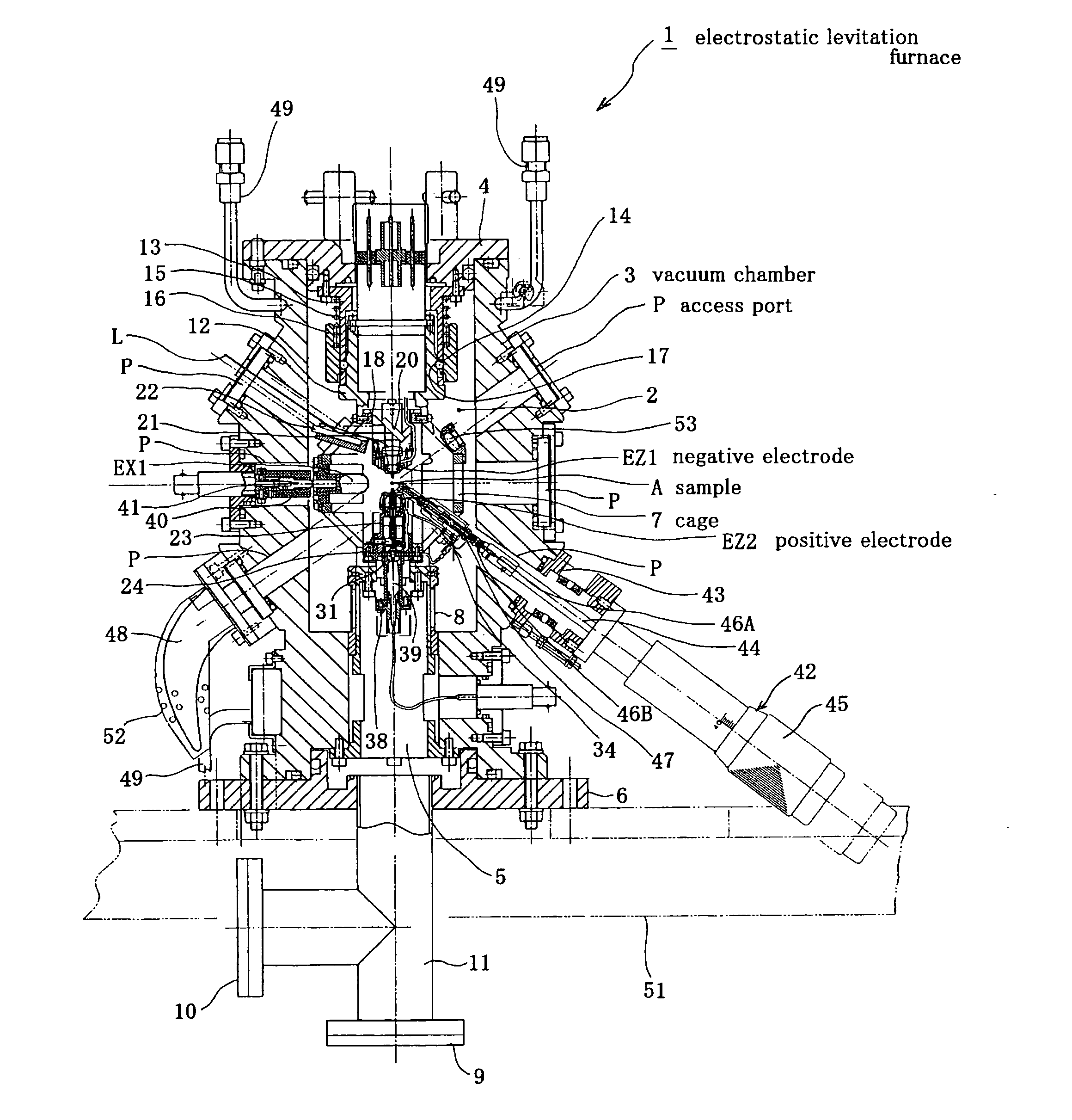
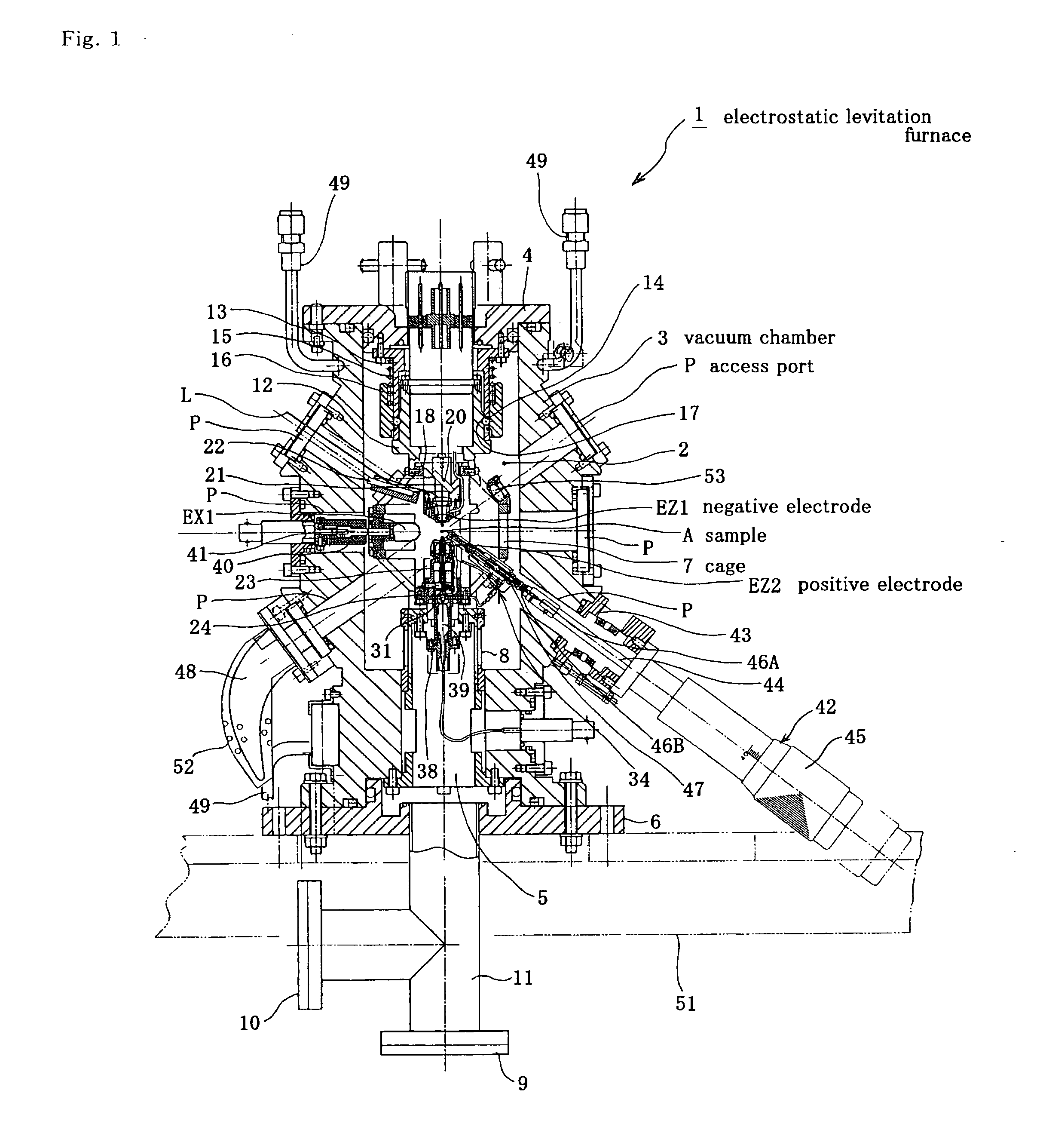
[0048] An electrostatic levitation furnace 1 shown in FIGS. 1 to 3 is provided with a vacuum chamber 3 forming a space 2 having nearly cylindrical shape opened in the vertical direction, a cover plate 4 for blocking the upper side of the vacuum chamber 3 in airtight, an electrode-base fixing pedestal 5 having a pipe-like shape and inset coaxially from lower side of the vacuum chamber 3, and a fitting flange 6 fixed to the underside of the vacuum chamber 3 in airtight, and this furnace 1 is secured to a base plate 51 shown with two-dot chain lines through the fitting flange 6.

[0049] The vacuum chamber 3 has an octagonal section and a sidewall divided into three parts i...


PUM


Abstract

An electrostatic levitation furnace is improved by providing three pairs of electrodes opposed to each other respectively on three axes perpendicularly intercepting each other at a position where the sample is to be levitated in the vacuum chamber, and disposing a plurality of access ports, which are directed to the position of the sample, to the vacuum chamber tree-dimensionally, whereby the accessible direction against the sample is diversified, it becomes possible to improve the degree of freedom in distribution of various apparatuses and easily cope with increase of apparatuses.

Description

TECHNICAL FIELD [0001] This invention relates to an electrostatic levitation furnace, which is used for suspending a charged sample in a levitation state in an electrostatic field generated between electrodes and subjecting the sample to heating process. BACKGROUND ART [0002] There is an electrostatic levitation furnace as a conventional levitation furnace, which is provided with a flat and nearly cylindrical shaped vacuum chamber, a pair of main electrodes disposed on Z-axis that is an axis of this vacuum chamber, a pair of auxiliary electrodes respectively disposed on X-axis and Y-axis intersecting perpendicularly to the Z-axis, and a plurality of access ports disposed two-dimensionally in a periphery of the vacuum chamber at predetermined spaces. The respective access ports are equipped with various apparatuses, such as a laser irradiator for heating the sample, a position detector for the sample, a thermal measuring device for the sample, an illuminator, a camera and so on. [000...

Claims


Application Information

Patent Timeline
Patent Type & Authority Applications(United States)
IPC IPC(8): F27B17/00F27B17/02F27D7/06F27D11/00F27D19/00F27D21/02H05B6/32
CPCF27B17/00F27B17/0016F27B17/02H05B6/32F27D11/00F27D19/00F27D21/02F27D7/06
Inventor KAWASAKI, KAZUNORIASAHI, HIROAKIMURAMATSU, SHOJITAKADA, TETSUYA
Owner IHI AEROSPACE CO LTD
Why Eureka
Try Eureka