

Tube joint
- Summary
- Abstract
- Description
- Claims
- Application Information
AI Technical Summary
Benefits of technology
Problems solved by technology
Method used
Image

Examples
Embodiment Construction
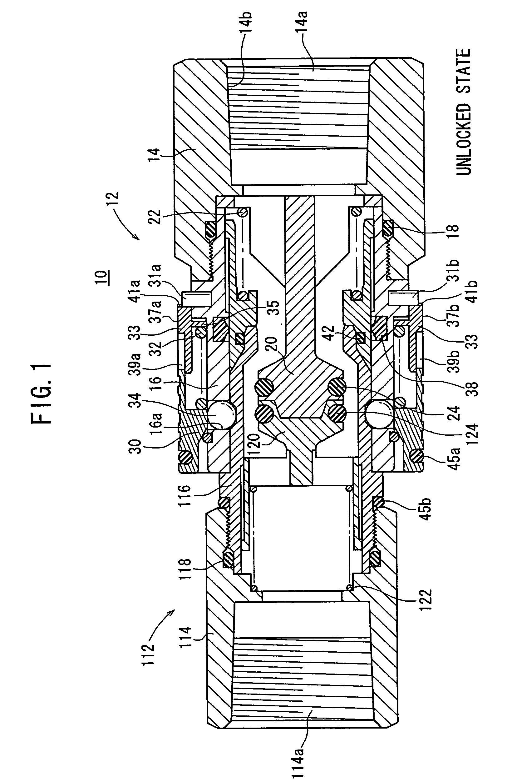
[0024] An explanation will be made below with reference to FIGS. 1 to 13 about embodiments of the tube joint according to the present invention. In the following explanation, in order to specify the direction, each of the socket and the plug is described in such a manner that the frontward direction and the front end reside in the side on which they are connected to one another, and the rearward direction and the rear end reside in the opposite side in the direction in which each the socket and the plug is connected to another tube passage (or a hose).
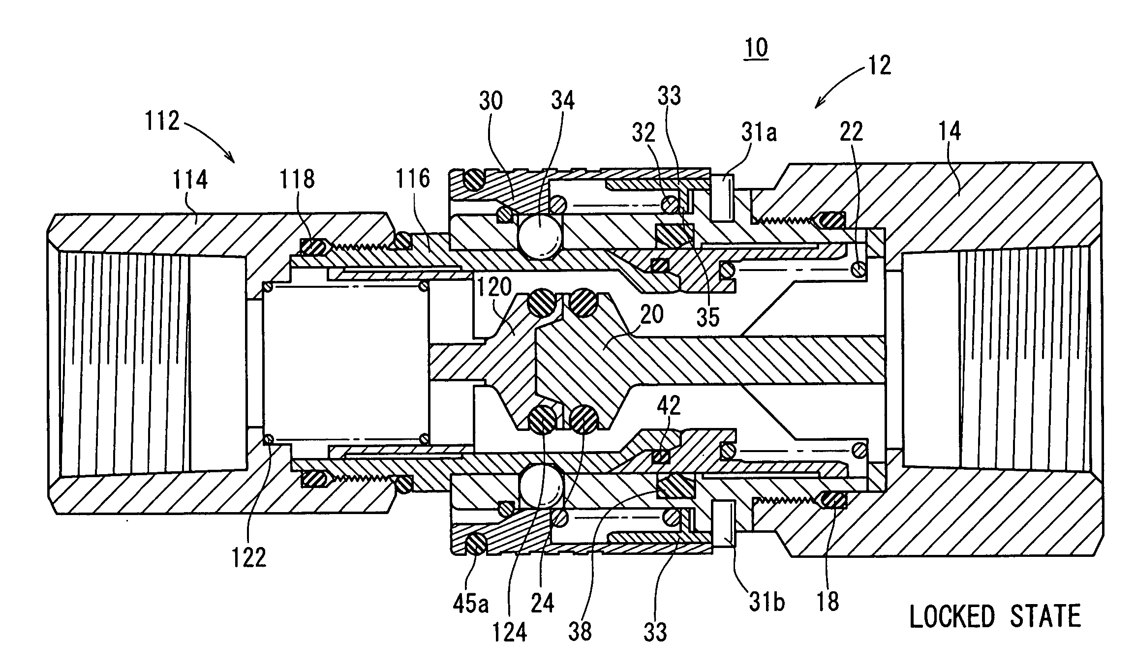
[0025] As shown in FIG. 1, a tube joint 10 according to a first embodiment comprises a socket 12 and a plug 112.
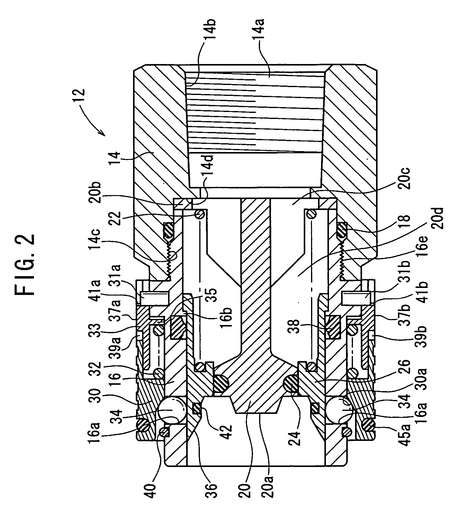
[0026] At first, an explanation will be made with reference to FIG. 2 about the socket 12 in the separated state.
[0027] In this description, the separated or disengaged state refers to the state in which the socket 12 and the plug 112 are separated from each other. On the other hand, the connected or coupled state refers t...
PUM
 Abstract
Description
Claims
Application Information