Swinging bob toy with liquid-containing bobs

Active Publication Date: 2005-03-03
SHAW LAURENCE J
View PDF16 Cites 5 Cited by
  • Summary
  • Abstract
  • Description
  • Claims
  • Application Information

AI Technical Summary

Problems solved by technology

Unfortunately, the limited ranges in the densities of solid low-density and high-density materials limits the degree to which the operation ratio X can be maximized, and ways in which the middle bob may be constructed.
Furthermore, the inclusion of a metal weight contributes substantially to the cost of the toy.

Method used


Image

  • Swinging bob toy with liquid-containing bobs
  • Swinging bob toy with liquid-containing bobs
  • Swinging bob toy with liquid-containing bobs

Examples


Embodiment Construction

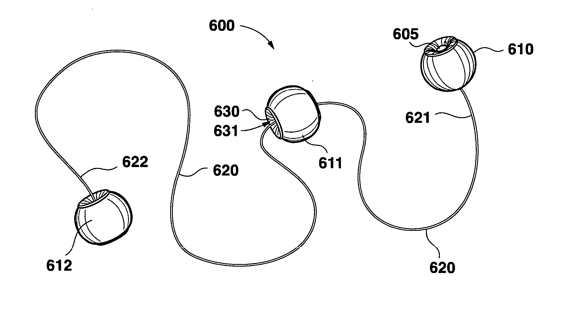
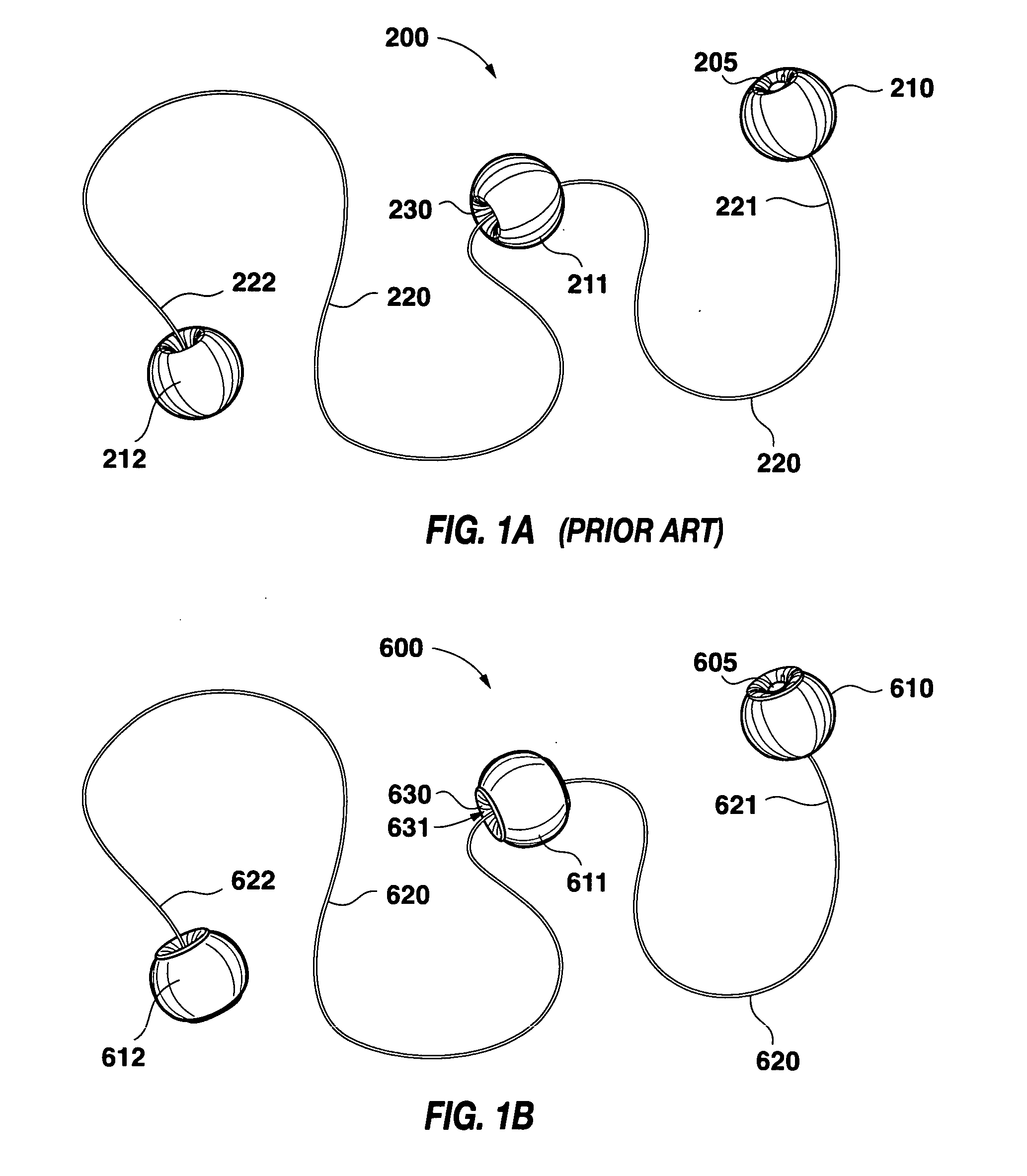
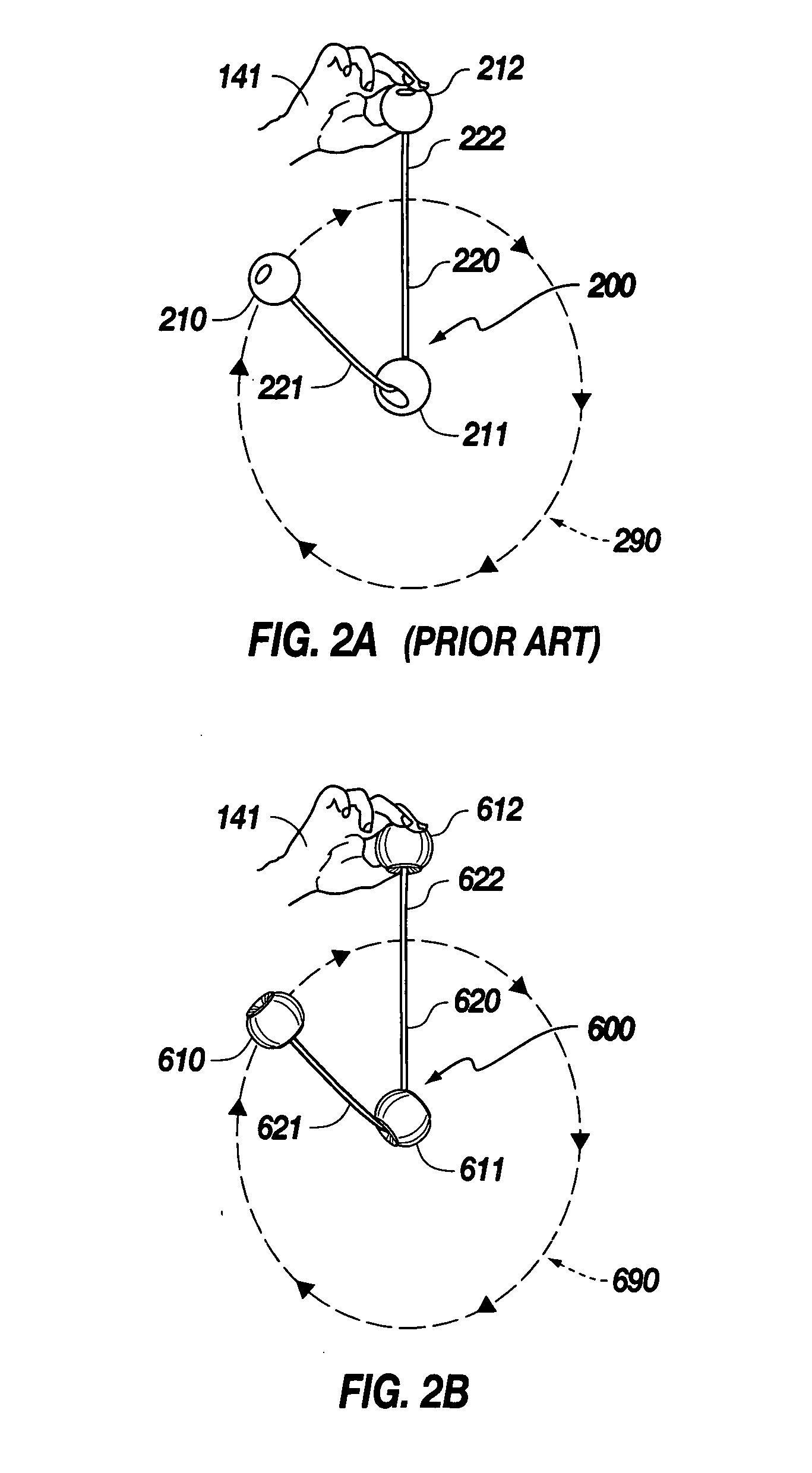
A swinging bob toy (600) according to the present invention is shown in FIG. 1B. As is the case with the swinging bob toy (200) of the prior art depicted in FIG. 1A, the swinging bob toy (600) of the present invention consists of three bobs (610), (611) and (612) on a string (620), with the middle bob (611) having a bore (632) through which the string (620) passes, thereby allowing the middle bob (611) to slide along the string (620). The end bobs (610) and (612) are fixed on the string (620) at the ends (621) and (622) thereof by pins (605) and (not visible in FIG. 1A) lodged into the bores of the end bobs (610) and (612), respectively. Alternatively, the bobs (210) and (212) may be constrained on the string (220) by knots at each end (221) and (222) of the string (220) having diameters larger than the bores of the end bobs (210) and (212), respectively. As shown in FIG. 2B, the toy (600) is operated by holding an end bob (612), and oscillating the hand (141) to cause the other two...


PUM


Abstract

A swinging bob toy having an outer bob and middle bob on a string, with the middle bob having a bore through which the string passes to allow the middle bob to slide along the string. The middle bob has a substantially toroidal, liquid-containing bladder. The mass of the liquid contributes substantially to the overall mass of the middle bob, but the viscosity of the liquid and the dimensions of the bore of the toroid are such that the dynamic moment of inertia (i.e., a moment of inertia dependent on linear and / or rotational velocity and / or acceleration, of a history thereof) is small as the middle bob begins its rotation as the outer bob passes the top of its orbit. The viscosity of the liquid is small enough that as the outer bob traverses the top of its orbit the dynamic moment of inertia is small and the string does not tangle about the middle bob, yet large enough that as the outer bob traverses the bottom of its orbit the rotation of the middle bob is slowed and the string tension does not exhibit a rapid peak.

Description

BACKGROUND OF THE INVENTION The present invention is directed to swinging bob toys with a sliding middle bob having a low moment of inertia about an axis perpendicular to the bore axis of the middle bob, and more particularly to swinging bob toys with a sliding middle bob having a low transient moment of inertia about an axis perpendicular to the bore axis of the middle bob due to movable components within the middle bob. As shown in FIG. 1A, a swinging bob toy (200) consists of three bobs (210), (211) and (212) on a string (220), with the end bobs (210) and (212) constrained at the ends (221) and (222) of the string (220), and the middle bob (211) having a bore (230) through which the string (220) passes, thereby allowing the middle bob (211) to slide along the string (220). The end bobs (210) and (212) are fixed on the string (220) at the ends (221) and (222) thereof by pins (205) and (not visible in FIG. 1A) lodged into the bores of the end bobs (210) and (212), respectively. (...

Claims


Application Information

Patent Timeline
IPC IPC(8): A63B37/08A63B43/00A63B67/08A63B67/10A63B69/00A63H1/22A63H33/00A63H33/18G01C15/10
CPCA63B43/007A63B67/08A63H33/18A63B69/0079A63B2037/085A63B67/10
Inventor SHAW, LAURENCE J.
Owner SHAW LAURENCE J
Why Eureka
Try Eureka