Water closet flange hub assembly

a technology for flange hubs and water closets, applied in water closets, water installations, construction, etc., can solve the problems of high labor intensity and high cost of replacemen

Inactive Publication Date: 2005-03-10
GREENE DENNIS J
View PDF10 Cites 38 Cited by
  • Summary
  • Abstract
  • Description
  • Claims
  • Application Information

AI Technical Summary

Benefits of technology

[0011] With the cylindrical pipe of the water closet hub positioned within the base, the toilet mounting flange is then secured to the floor using conventional fasteners.

Problems solved by technology

Such replacement is highly labor intensive and therefore expensive.

Method used


Image

  • Water closet flange hub assembly
  • Water closet flange hub assembly
  • Water closet flange hub assembly

Examples


Embodiment Construction

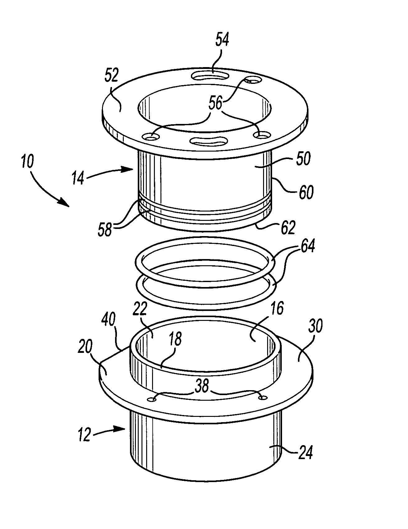
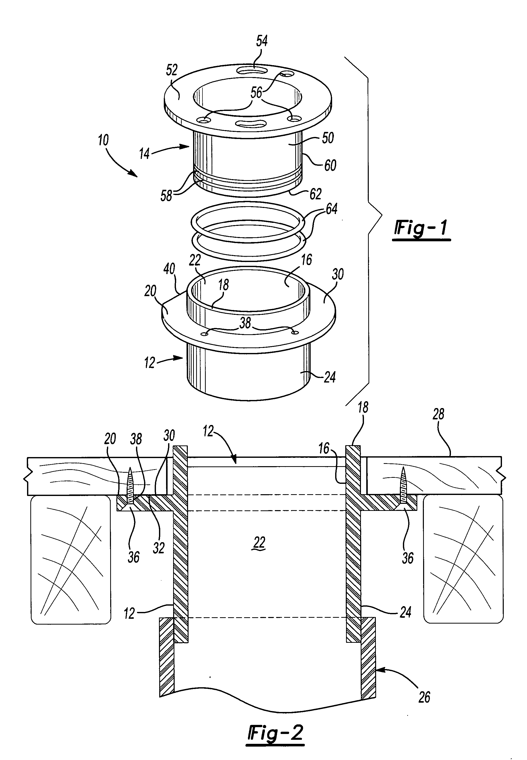
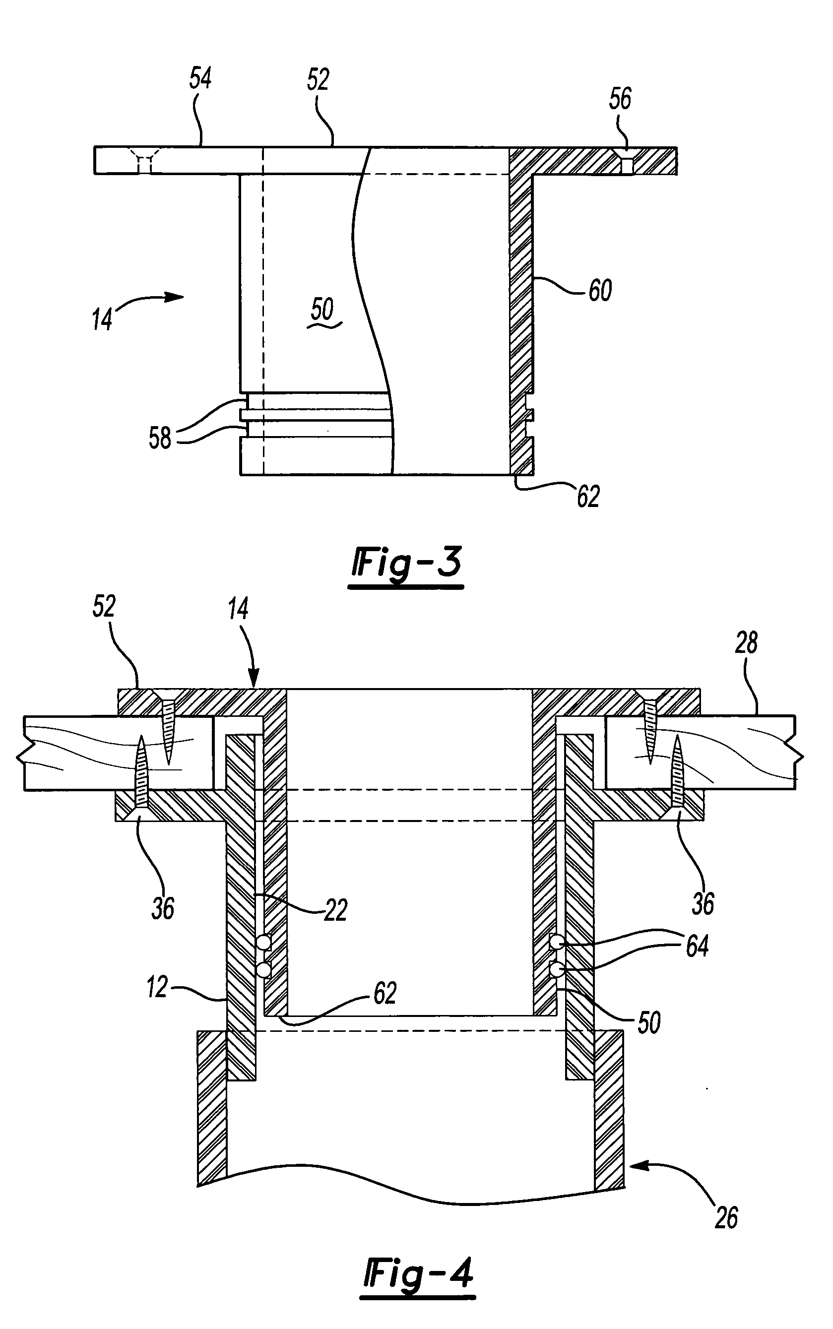
[0017] With reference first to FIG. 1, a preferred embodiment of the water closet flange hub assembly 10 of the present invention is shown. The water closet flange hub assembly 10 includes both an annular base 12 as well as a water closet hub 14. Both the annular base 12 and water closet hub 14 are preferably of a one-piece plastic construction.

[0018] With reference now particularly to FIG. 2, the annular base 12 is shown in greater detail and includes a central cylindrical throughbore 16. The annular base 12, furthermore, is generally tubular and cylindrical in shape and includes a radially outwardly extending flange 20 at a position spaced downwardly from an upper open end 22 of the base 12. A lower end 24 of the base 12 is fluidly connected to a waste system 26 (only partially illustrated) of a structure. Typically, the waste system 26 is also constructed of plastic and the base 12 is secured to the waste system 26 by chemical welding.

[0019] Still referring to FIG. 2, the hub 1...


PUM


Abstract

A water closet flange hub assembly for use with a floor. The assembly includes an annular base having a central through opening and which is mounted to the floor. A water closet hub includes a tubular and cylindrical pipe which is dimensioned to be slidably and adjustably positioned within the base opening. The hub also includes an outwardly extending toilet mounting flange at one end of the pipe. A fluid seal is disposed between the pipe of the water closet hub and the annular base to fluidly seal the base and hub together at an adjusted position of the water closet hub. The water closet hub is then secured to the floor by fasteners.

Description

RELATED APPLICATION [0001] This application claims priority of U.S. Provisional Patent Application Ser. No. 60 / 501,239 filed Sep. 8, 2003, which is incorporated herein by reference.BACKGROUND OF THE INVENTION [0002] I. Field of the Invention [0003] The present invention relates to plumbing fittings and, more particularly, to a water closet flange hub assembly. [0004] II. Description of Related Art [0005] The previously known water closet flange typically comprise a tubular and cylindrical plastic pipe having an outwardly extending flange adjacent its upper end. The pipe is secured, typically by chemical welding, to the waste plumbing system of the structure so that the flange is level with the building floor. A toilet is then secured to the flange by conventional fasteners. [0006] In some situations, for example where a new floor covering is installed, the level of the floor changes from its prior level. When this occurs, the flange is no longer even with the floor surface. When thi...

Claims


Application Information

Patent Timeline
Patent Type & Authority Applications(United States)
IPC IPC(8): E03D11/16E03D11/17
CPCE03D11/17E03D11/16
Inventor GREENE, DENNIS J.
Owner GREENE DENNIS J
Why Eureka
Try Eureka