Joint heat

a heating device and joint technology, applied in the field of joint heat, can solve the problems of not providing the needed heat to all the muscle groups associated, people experience ‘hot spots', etc., and achieve the effect of capturing the majority of the hea

Active Publication Date: 2005-03-10
LEWIS DANIEL HOUSTON
View PDF9 Cites 21 Cited by
  • Summary
  • Abstract
  • Description
  • Claims
  • Application Information

AI Technical Summary

Benefits of technology

[0015] On the other hand, the pocket formed by the unique, three-dimensional, curved structure of the instant device provides a comfortable envelope that completely enwraps and silhouettes the entire area of these three targeted joints, capturing most of the heat.

Problems solved by technology

The flat electric heating pad is not designed to blanket the entire shoulder, elbow or knee, and, therefore, will not provide the needed heat to all of the muscle groups associated with these joints, and will allow most of the heat to escape from around the unsecured edges of the pad.
As a result of this “square peg / round hole” configuration, some people experience ‘hot spots’ from the unevenness caused by this misuse.

Method used


Image

  • Joint heat
  • Joint heat
  • Joint heat

Examples


Embodiment Construction

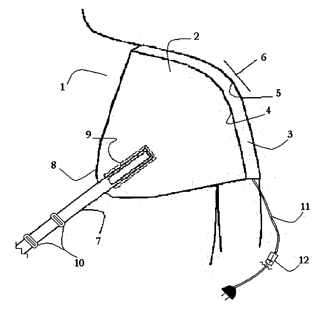
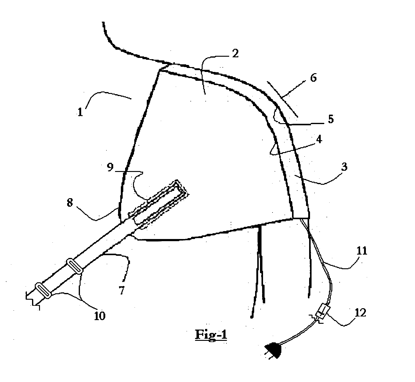
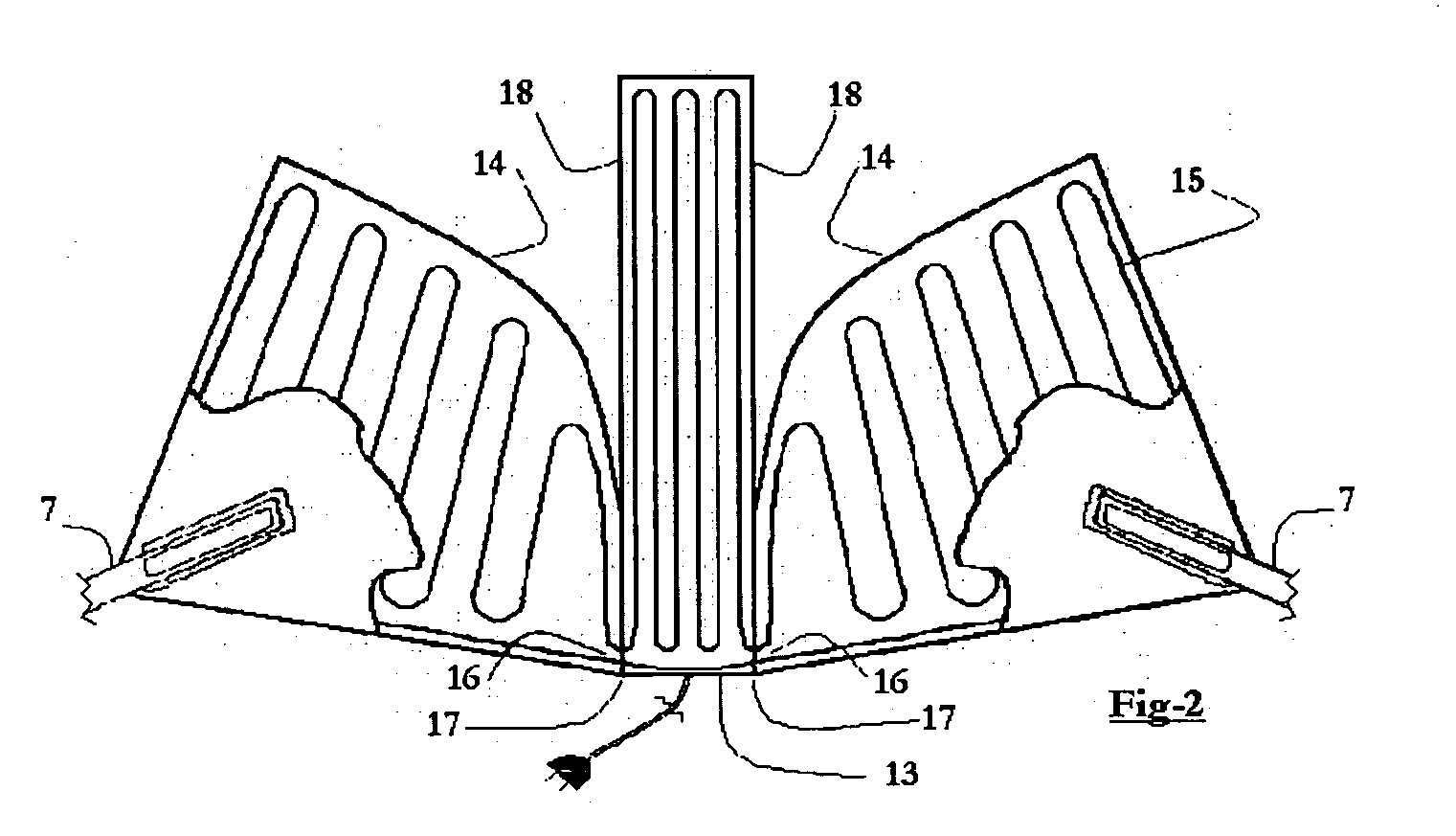
[0018] The instant electric heating device is actually three heating pads with one electric source and one controller, sewn together, with their enclosed heating elements connected at a narrow, one inch outer edge of the connected pads.

[0019] The isolation of this connection to the outer edge allows for the free flexure of the pads at the their connected seams.

[0020] One of the three pads is rectangular in shape—approximately 3½ inches to 4½ inches in width and approximately 14 inches to 16 inches in length. This becomes the center panel of the device, to which two triangular side panels are attached.

[0021] The two triangular side panels are duplicates of each other, and will become the sides or walls of the device. They are cut in the basic form of a triangle, with two edges being straight and the third being curved in an arch that follows the silhouette of a normal, at rest, human shoulder.

[0022] The two straight edges of each triangular side panel are approximately 11 inches ...


PUM


Abstract

An electric heating device that is constructed in a unique fashion that allows it to be drapeable so that its three-dimensional, ‘scoop-like’ shape fits the curvature of a relaxed shoulder, a crooked knee or a crooked elbow, and is held in place by an adjustable strap whose ends are attached to the device. The heating element configuration that is contained within a singular, sealed, water-envelope tight vinyl envelope that is produced as one piece, with the three panels briefly connected at a point where the heating element wiring crosses from one panel to the other.

Description

REFERENCES [0001]551939December, 1895Weber128 / 403723797March, 1903Williams128 / 3791594053July, 1926Evans128 / 3792071706February, 1937Reach128 / 3802429583October, 1947Ogle128 / 3803178559April, 1965Fogel et al.219 / 5283889684June, 1975Lebold128 / 4034061897December, 1977Thykeson128 / 3794512830April, 1985Hulett et al.128 / 380Foreign Patent Documents191,084September, 1956OE128 / 3BACKGROUND OF THE INVENTION [0002] The present invention relates to an electric heating device, and more particularly to an electric heating device for providing bilateral heat for treatment of related muscle groups, tendons and nerve bundles associated with three body joints: the shoulder, elbow and knee. [0003] It is a well-known fact that heat is helpful in the therapeutic treatment of injured skeletal muscles and connective tissues. The application of increased heat causes the dilation of the blood vessels (vasodilatation) which increases blood flow to treated areas, thereby, speeding up the healing process. [0004] It...

Claims


Application Information

Patent Timeline
Patent Type & Authority Applications(United States)
IPC IPC(8): A61F7/02H05B3/34H05B3/44
CPCA61F7/007H05B3/10A61F2007/0228A61F2007/0001A61F2007/003H05B3/342H05B2203/003H05B2203/014A61P29/00A61P43/00C07C45/41C07C57/58C07C59/48C07C59/68C07C69/732C07C69/734C07C205/58C07D279/16G02B27/0972G02B27/0994C07C47/277
Inventor LEWIS, DANIEL HOUSTON
Owner LEWIS DANIEL HOUSTON
Why Eureka
Try Eureka