
Upward deploying inflatable knee bolster with mechanical guides

a knee bolster and mechanical guide technology, applied in the field of knee bolsters, can solve the problems of existing knee bolsters failing to address this shearing effect, the knee of a vehicle occupant is frequently susceptible to injury, and the ligaments and tendons in the knee to tear

Inactive Publication Date: 2005-03-24
KEY SAFETY SYST
View PDF19 Cites 27 Cited by
  • Summary
  • Abstract
  • Description
  • Claims
  • Application Information

AI Technical Summary

Benefits of technology

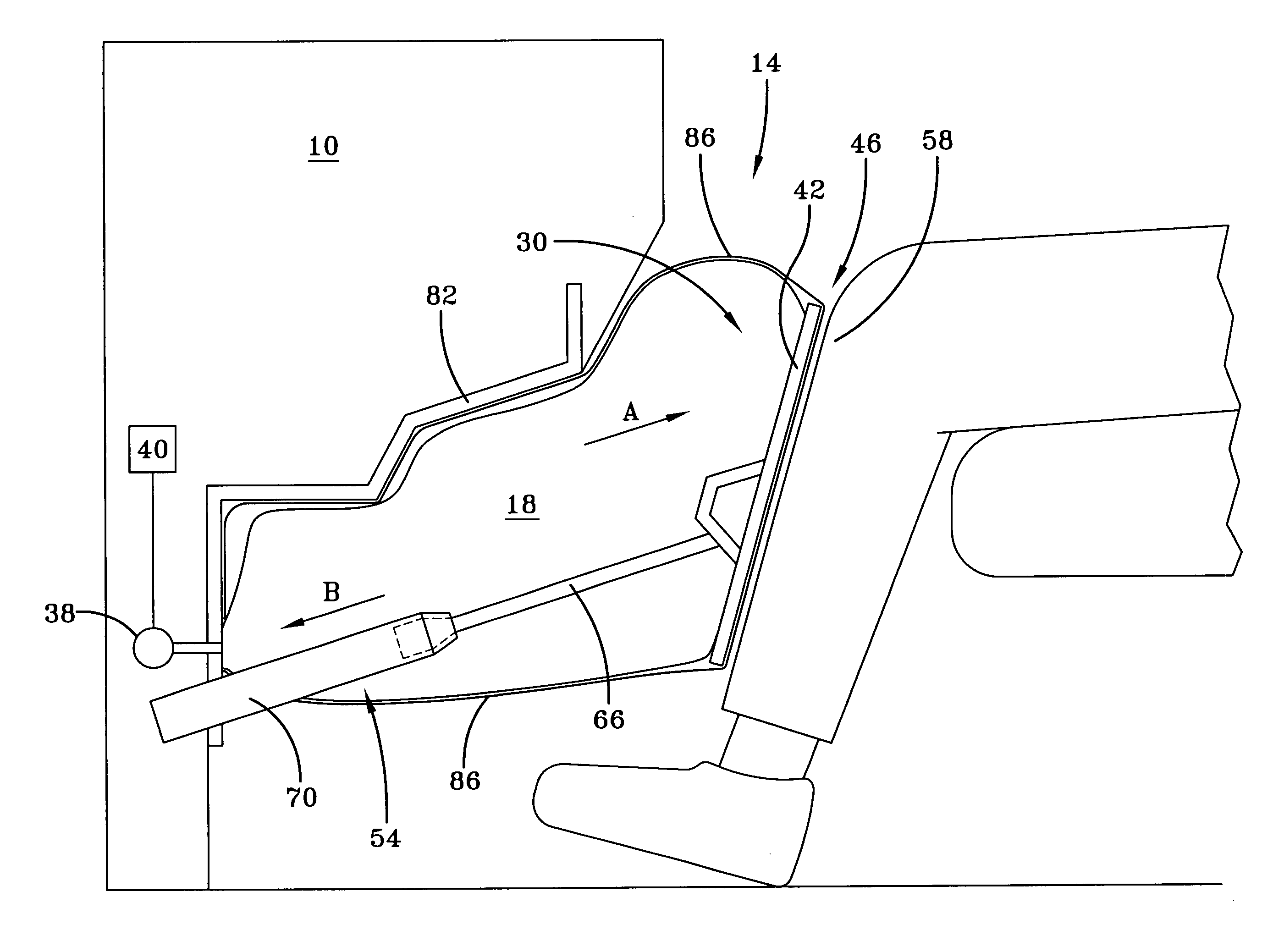
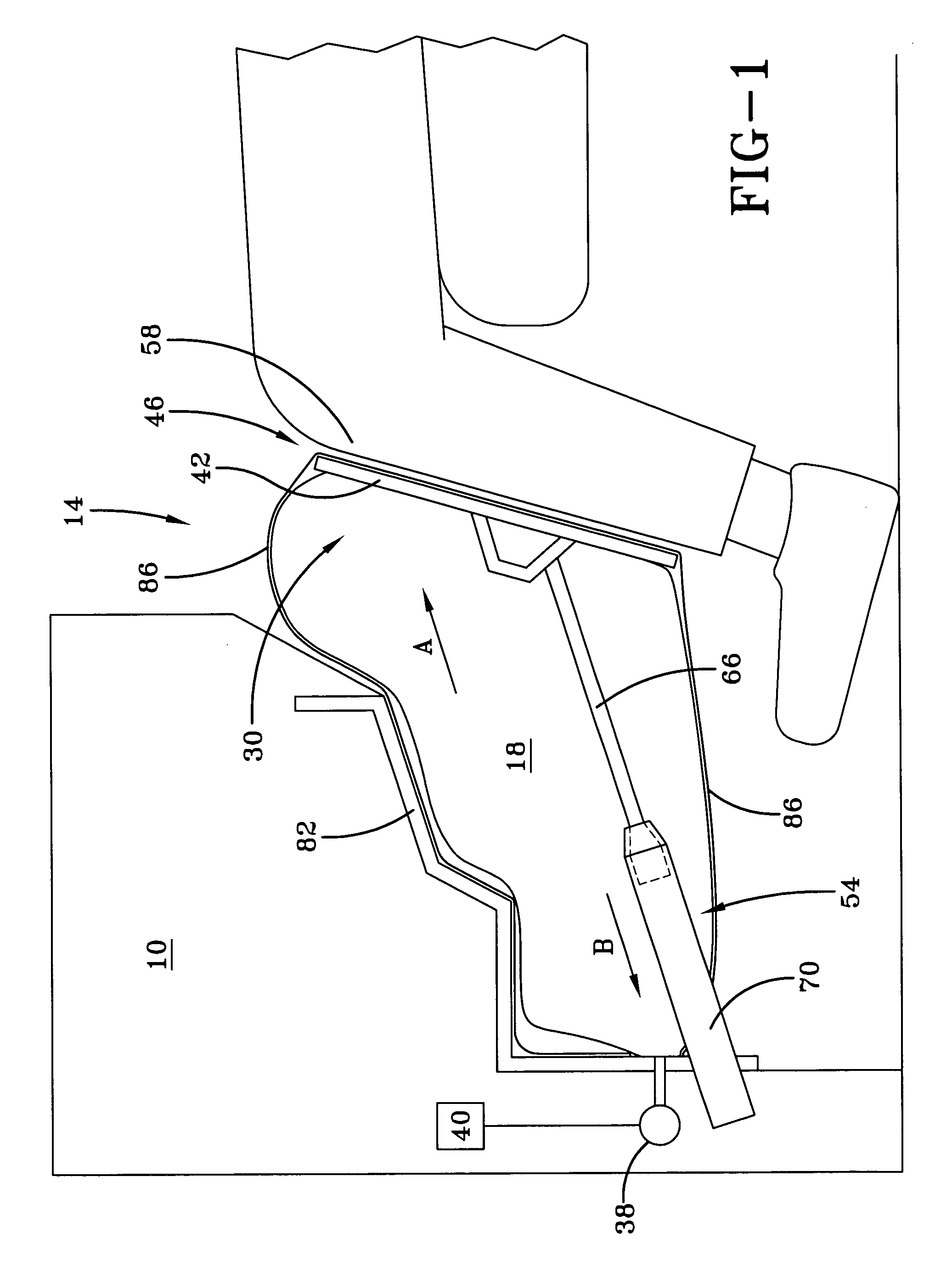
[0006] The present invention uses an air bag to advance a knee bolster toward an anticipated location of a knee of a vehicle occupant. The air bag has a deflated condition and an inflated condition. The air bag is inflated by an air bag inflator. In contrast to existing designs, the inventive knee bolster uses a guide structure attached to the bolster to direct the bolster along a generally linear path toward the knee. In this way, the bolster may focus its cushioning effect on the knee rather than on both the knee and the tibia while still providing the cushioning effect from an air bag.
[0009] The guide structure may expand and retract between the actuated position and the unactuated position so that the air bag may be allowed to deflate once the vehicle occupant has contacted the knee bolster. Moreover, by placing the knee bolster at the front area of the air bag, the knee bolster may advance quickly and directly to the anticipated location of the knee. The vehicle occupant will also have the benefit of the full cushioning effect of the air bag at this location. In this way, the knee bolster may move with the knee of the vehicle occupant to collapse the air bag from front to rear for a full cushioning.

Problems solved by technology

In a vehicle crash, the knee of a vehicle occupant is frequently susceptible to injury.
A significant number of knee injuries results from impact forces on the leg that cause the lower leg (tibia) to travel in an opposite direction to the path of the upper leg (femur).
As a consequence of this motion, the tibia shears relative to the femur, causing ligaments and tendons in the knee to tear.
Existing knee bolsters fail to address this shearing effect.
However, such an air bag does not prevent movement of the knee relative to the tibia because the air bag contacts both the knee and the tibia in deployment.
This alternative design does not offer the benefits of cushioning a vehicle impact with an air bag.

Method used


Image

  • Upward deploying inflatable knee bolster with mechanical guides
  • Upward deploying inflatable knee bolster with mechanical guides
  • Upward deploying inflatable knee bolster with mechanical guides

Examples


Embodiment Construction

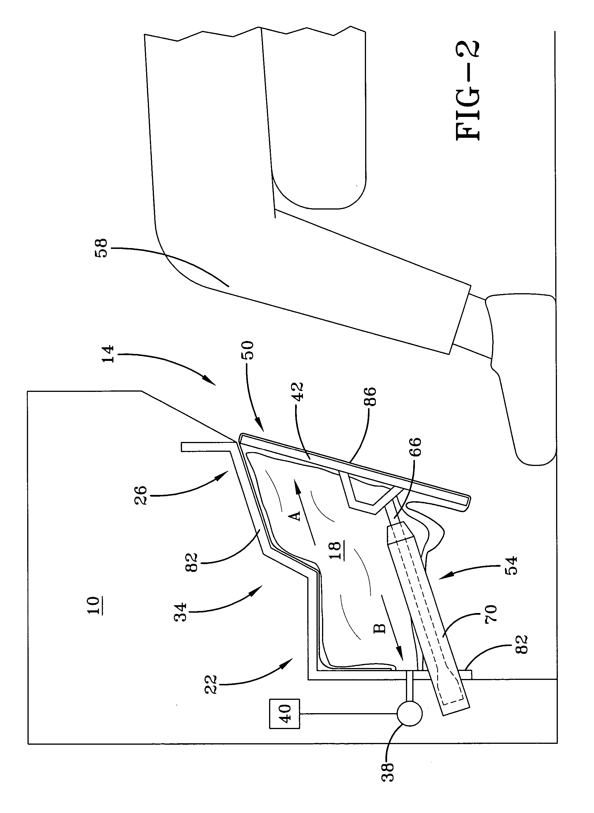
[0017]FIG. 1 illustrates a side view of inventive knee bolster 14. Inventive knee bolster 14 is located within vehicle 10, preferably under a vehicle instrument panel as shown. In FIG. 1, knee bolster 14 is shown with air bag 18 in inflated condition 30 while, in FIG. 2, air bag 18 is shown in deflated condition 34.

[0018] Inventive knee bolster 14 comprises air bag 18, air bag inflator 38, knee contact plate 42, and guide structure 54. In contrast to existing knee bolster designs, inventive knee bolster 14 uses guide structure 54 to direct knee contact plate 42 along linear path A to an anticipated location of a knee of a vehicle occupant 58.

[0019] The operation of inventive knee bolster 14 will now be explained. FIG. 2 illustrates knee bolster 14 with air bag 18 in deflated condition 34 and knee contact plate 42 in unactuated position 50. As shown, air bag 18 has rear area 22 and front area 26. The contact plate 42 is located at front area 26 of air bag 18 while air bag housing 8...


PUM


Abstract

A knee bolster for a vehicle has an air bag and an air bag inflator. The air bag has an inflated condition and a deflated condition. The air bag is attached to the knee bolster, which is moveable with the air bag. The knee bolster may move from an unactuated position when the air bag is in the deflated condition to an actuated position when the air bag is inflated. A guide structure, which is attached to the knee bolster directs the bolster along a linear path from the unactuated position to the actuated position.

Description

FIELD OF THE INVENTION [0001] This invention relates to a knee bolster for a vehicle. BACKGROUND OF THE INVENTION [0002] In a vehicle crash, the knee of a vehicle occupant is frequently susceptible to injury. A significant number of knee injuries results from impact forces on the leg that cause the lower leg (tibia) to travel in an opposite direction to the path of the upper leg (femur). As a consequence of this motion, the tibia shears relative to the femur, causing ligaments and tendons in the knee to tear. [0003] Existing knee bolsters fail to address this shearing effect. For example, one such design merely deploys an air bag in the vicinity of the knee of the occupant. However, such an air bag does not prevent movement of the knee relative to the tibia because the air bag contacts both the knee and the tibia in deployment. [0004] An alternative knee bolster design uses a mechanical carriage to direct a padded cushion toward the knee of the vehicle occupant. This design advances...

Claims


Application Information

Patent Timeline
Patent Type & Authority Applications(United States)
IPC IPC(8): B60R21/16B60R21/20B60R21/205B60R21/215B60R21/231
CPCB60R21/206B60R21/216B60R2021/23169B60R2021/2161B60R2021/2163B60R2021/161
Inventor ARWOOD, ROBERTBAUMBACH, ERICBLOCK, ROBERTCOOPER, JOHNBEDEKAR, KAUSTUBHATKINSON, PAT
Owner KEY SAFETY SYST
Learn More