Wear-adaptable running tread

a running tread and wear-adaptable technology, applied in the direction of non-skid devices, transportation and packaging, other domestic objects, etc., can solve the problems of more wear and irregular wear at the edges, and achieve the effect of adapting the rigidity level of the tread, reducing or even preventing the appearance of localized wear, and reducing the risk of rubber splits

Inactive Publication Date: 2005-04-21
MICHELIN RECH & TECH SA
View PDF7 Cites 23 Cited by
  • Summary
  • Abstract
  • Description
  • Claims
  • Application Information

AI Technical Summary

Benefits of technology

[0014] With a tread according to the invention, each cavity opens not in its entirety (that is to say over its entire length) onto the running surface after partial wear but rather progressively. In this manner, new grooves or incisions are created which define new tread pattern elements between which there exist bridges of rubber, at least in a first phase; this has the effect of adapting the rigidity levels of the tread and of reducing or even preventing the appearance of localized wear on these new tread pattern elements (this irregular wear appearing instead from the time when the new elements have just been formed).
[0015] On the other hand, the progressive formation of grooves or incisions on the running surface is beneficial since it has been noted that it reduces the risk of splits forming in the rubber.
[0021] It was noted that the rolling resistance of a tire according to the invention was improved relative to a tire provided with cavities not having the characteristics of the cavities according to the invention; this reduction in rolling resistance is probably associated with limitation of the deformation of the tread at the time when new grooves are formed.

Problems solved by technology

The tread patterns produced according to this teaching result in a significant improvement; however, under certain conditions irregular wear may develop at the edges (or ridges) of the tread pattern elements newly created by the new grooves formed at the moment when the channels reach the running surface.
Irregular wear means wear which develops more over certain regions of the tread and which does not develop homogeneously within the thickness of the tread; this wear may necessitate premature withdrawal of the tire provided with such a tread.

Method used


Image

  • Wear-adaptable running tread
  • Wear-adaptable running tread
  • Wear-adaptable running tread

Examples


Embodiment Construction

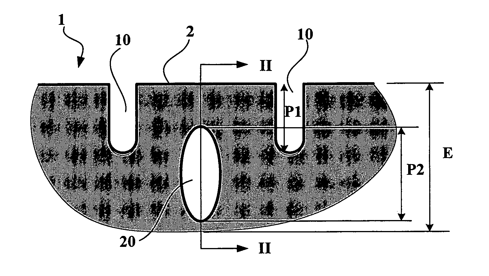
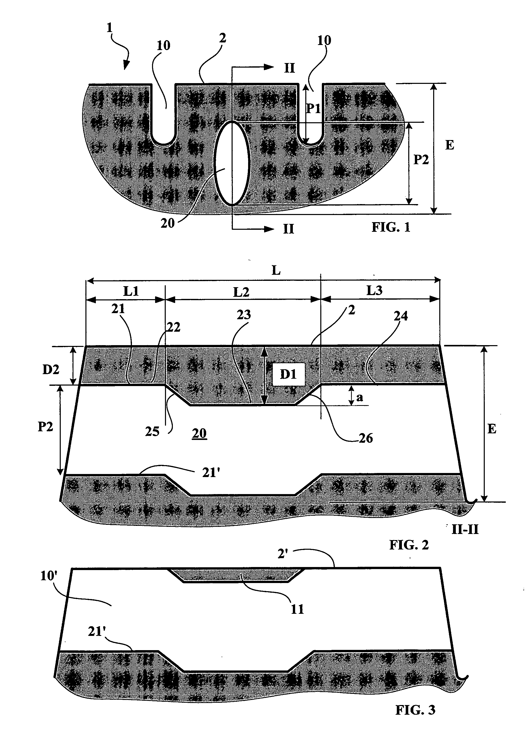
[0029]FIG. 1 shows a partial section through a tread 1 according to the invention comprising a plurality of first grooves 10 defining relief elements forming a tread pattern when new (that is to say not worn). This tread has a running surface when new 2 intended to come into contact with the roadway during travel of a tire provided with this tread.

[0030] These grooves 10 have a depth P1 less than the total thickness E of the tread (in the present case, this depth P1 is substantially equal to 50% of the thickness E).

[0031] Furthermore, a cross-section is shown through a cavity 20 entirely situated beneath the running surface 2 when new; in the section plane, this cavity has a substantially elliptical section whose large axis (substantially perpendicular to the running surface 2) is of the length P2 substantially equal to the depth P1. This cavity is intended to form a new groove once partial wear of the tread has brought the upper part of said cavity up to the new running surface. ...


PUM

PropertyMeasurementUnit
widthaaaaaaaaaa
thicknessaaaaaaaaaa
heightaaaaaaaaaa

Abstract

A tread of a total thickness E for tires, comprising, when new: a running surface intended to be in contact with the roadway during travel; a plurality of first cutouts of a depth of less than the thickness of the tread and defining tread pattern elements of a height less than the total thickness of the tread; a plurality of cavities subjacent the running surface when new and extending over an average length L, each of these cavities being intended to form at least one new groove or incision after partial wear of the tread; each cavity delimited by the rubber of the tread having an upper generatrix beneath the running surface when new; this tread being characterized in that, for each cavity, the upper generatrix follows an undulating profile having a series of recesses and elevations, the amplitude of these recesses and elevations being at least 10% of the depth of the new grooves or incisions created.

Description

FIELD OF INVENTION [0001] The invention relates to tread patterns for tires and in particular for tires intended to be fitted on heavy vehicles. BACKGROUND OF INVENTION [0002] In order to ensure that a tread performs optimally on all types of ground (dry or wet), it is known to provide this tread with a tread pattern formed of a plurality of tread pattern elements defined by cutouts (adopting the form either of grooves or of incisions), these cutouts opening onto the running surface of the tread when new. The function of these cutouts is to create ridges for cutting through the film of liquid which may be present on the roadway and to serve as passages for the flow of the same liquid in order to improve the safety of a vehicle fitted with such tires on ground covered in liquid. [0003] However, the presence of deep cutouts allowing the technical effects mentioned above to be benefited from for the entire service life of the tread (corresponding generally to the wear limit acceptable ...

Claims


Application Information

Patent Timeline
Patent Type & Authority Applications(United States)
IPC IPC(8): B29D30/06B60C11/00B60C11/03B60C11/04B60C11/12B60C11/13
CPCB29D30/0606B29D2030/061B60C11/00B60C11/13B60C11/032B60C11/12B60C11/03Y10S152/03B60C11/0323
Inventor LOPEZ, JOSE MERINO
Owner MICHELIN RECH & TECH SA
Why Eureka
Try Eureka