Breakaway antenna

a technology for antennas and antennas, applied in the direction of antennas, antenna details, antenna adaptation in movable bodies, etc., can solve the problems of large, heavy duty antennas mounted on military vehicles, antennas to break, and cannot withstand the size and conditions of military antennas

Inactive Publication Date: 2005-05-05
TECHN & MANAGEMENT SERVICES CORP
View PDF13 Cites 20 Cited by
  • Summary
  • Abstract
  • Description
  • Claims
  • Application Information

AI Technical Summary

Benefits of technology

[0004] The present invention provides an antenna mount which secures an antenna in an upright position while allowing the antenna to become disengaged from the upright position when the antenna encounters a low barrier or low clearance. Upon such imp

Problems solved by technology

This type of construction, while acceptable for light duty antennas such as the antennas found on many cars, it is unsuitable for the large, heavy duty antennas mounted on military vehicles.
When a heavy duty type antenna is mounted on a moving military vehicle and the antenna encounters an obstruction overhead of the vehicle, the impact of the antenn

Method used


Image

  • Breakaway antenna
  • Breakaway antenna
  • Breakaway antenna

Examples


Embodiment Construction

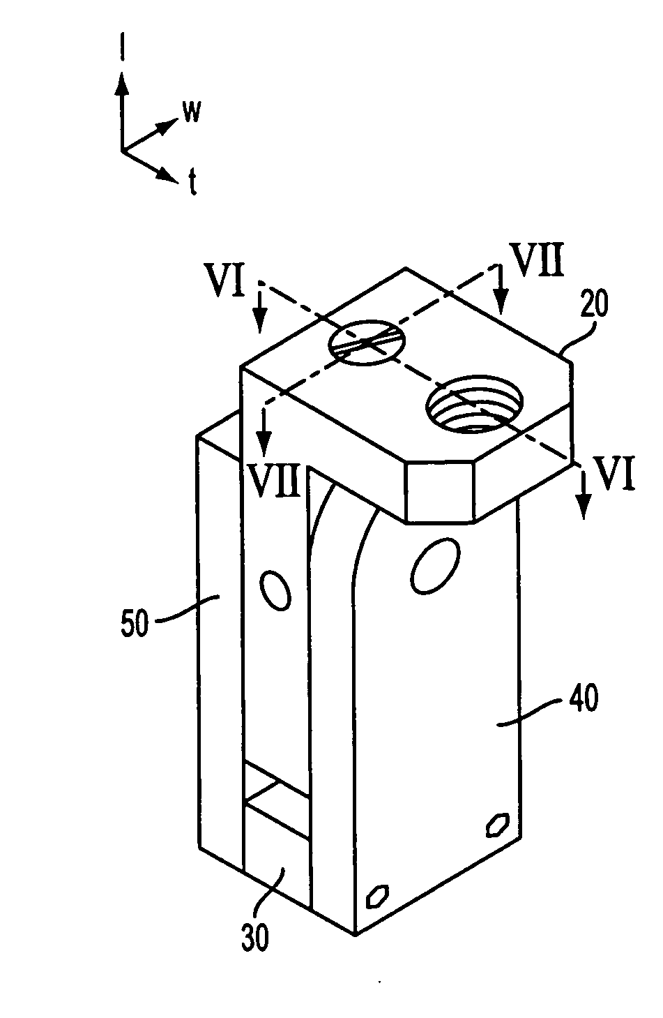
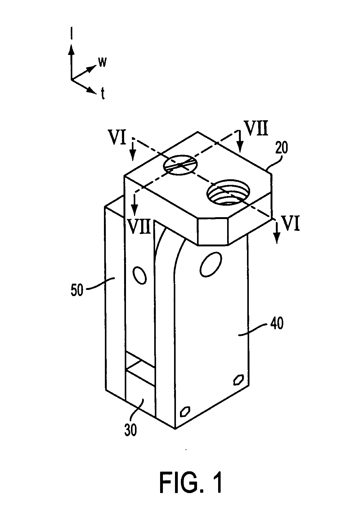
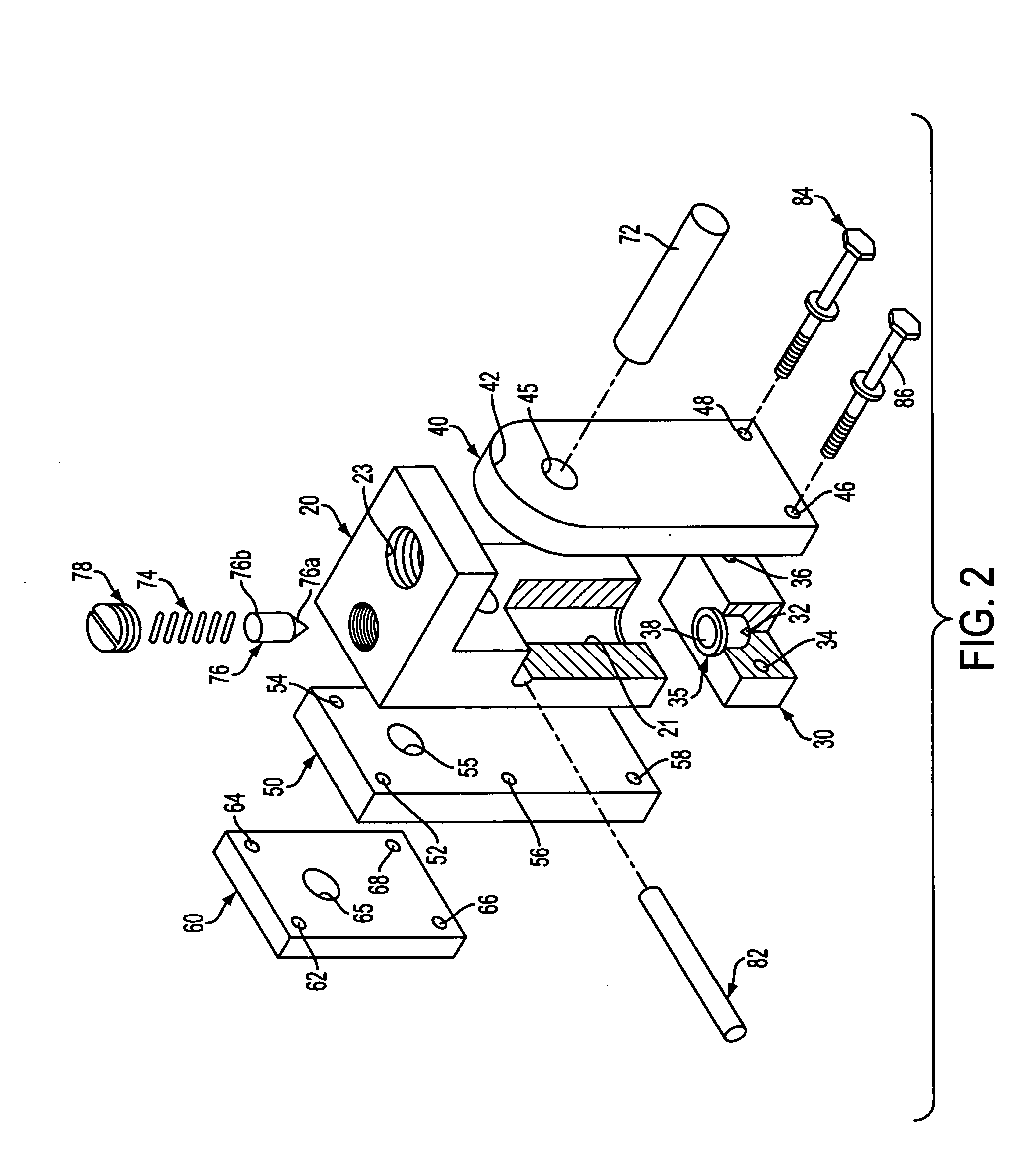
[0018]FIG. 1 shows an antenna mount 10 according to an embodiment of the present invention, while FIG. 2 shows an exploded view of the antenna mount 10. Generally, the antenna mount 10 includes a front plate 40, a back plate 50, a separator 30 and a rotator 20.

[0019] As best seen in FIG. 2, front plate 40 has a pivot bore 45 formed through the thickness of the plate at an upper region thereof, and two parallel bores 46, 48 formed through the plate and near the bottom corners of the plate. Preferably, though not necessarily, the upper end of the front plate 40 has a rounded contour 42.

[0020] The structure of the back plate 50 is similar to that of the front plate 40 in that the back plate 50 also has a pivot bore 55 extending through the thickness of the plate and a pair of parallel bores 58 (only one shown in FIG. 2) formed through the plate near the bottom corners thereof. Additionally, back plate 50 also includes two additional pairs of bores 52, 54 and 56 (only one shown in FIG...


PUM


Abstract

An antenna mount includes a frame formed by a front plate and a rear plate connected by a separator, which has a concave seat centrally located on its upper surface. A rotator element is pivotally secured between the front and rear plates, and is rotatable either clockwise or counterclockwise through the support frame. The upper portion of the rotator has a threaded opening into which an antenna can be mounted, while a spring mounted piston is provided at the bottom end of the rotator. When an antenna is mounted in the rotator and is upright, the piston is securely engaged on the seat. The antenna mount is installed on a vehicle so that upon encountering an obstacle while moving either forward or backward, the spring mounted piston becomes disengaged from the seat, causing the rotator and antenna to pivot either forward or backward in response to the force. The antenna can be reset by lifting the antenna until the antenna mount returns to a locked position and the antenna is again upright.

Description

FIELD OF THE INVENTION [0001] The present invention relates to a mounting device for antennas, and more particularly for antennas used on vehicles which use tall antennas. BACKGROUND OF THE INVENTION [0002] A typical aerial antenna mounted to the exterior body of the vehicle is constructed as a series of concentric segments which allow the antenna to be extended to a maximum length by “stretching” the antenna so that its segments are linearly arranged, and to be retracted by collapsing the segments down to the length of one segment. This type of construction, while acceptable for light duty antennas such as the antennas found on many cars, it is unsuitable for the large, heavy duty antennas mounted on military vehicles. As military equipment becomes more sophisticated and more reliant on radio or other airwave transmissions, more and more equipment are requiring mounted antennas mounted on the vehicles. Such military antennas are typically at least 15-20 feet tall and 1.5″ or larger...

Claims


Application Information

Patent Timeline
IPC IPC(8): H01Q1/08H01Q1/12H01Q1/32
CPCH01Q1/084H01Q1/325H01Q1/1207H01Q1/088
Inventor PICK, STEVE J.
Owner TECHN & MANAGEMENT SERVICES CORP
Why Eureka
Try Eureka