Failsafe hydraulic circuit

Inactive Publication Date: 2005-06-23
AISIN AW CO LTD +1
View PDF8 Cites 18 Cited by
  • Summary
  • Abstract
  • Description
  • Claims
  • Application Information

AI Technical Summary

Benefits of technology

[0016] According to a fourth aspect of the present invention, the oil pressure that linearly corresponds to the engaging pressure supplied to one of the two hydraulic servos can be input to a corresponding one of the two oil pressure detector devices, so that the engaging pressure supplied to the one of the hydraulic servos can be relatively dir

Problems solved by technology

However, the above-described failsafe hydraulic circuit has the following problem.
That is, although the oil pressure switch is able to detect whether the operation of the fa

Method used


Image

  • Failsafe hydraulic circuit
  • Failsafe hydraulic circuit
  • Failsafe hydraulic circuit

Examples


embodiment 1

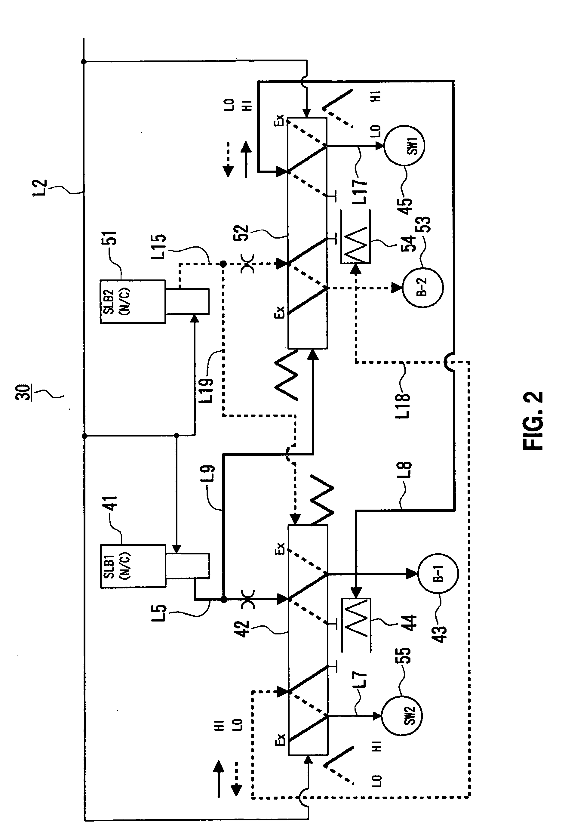
[0023] A failsafe oil passage structure 30 (see FIGS. 2 and 3) in accordance with the present invention is applicable to, for example, a hybrid drive apparatus mounted in a motor vehicle.

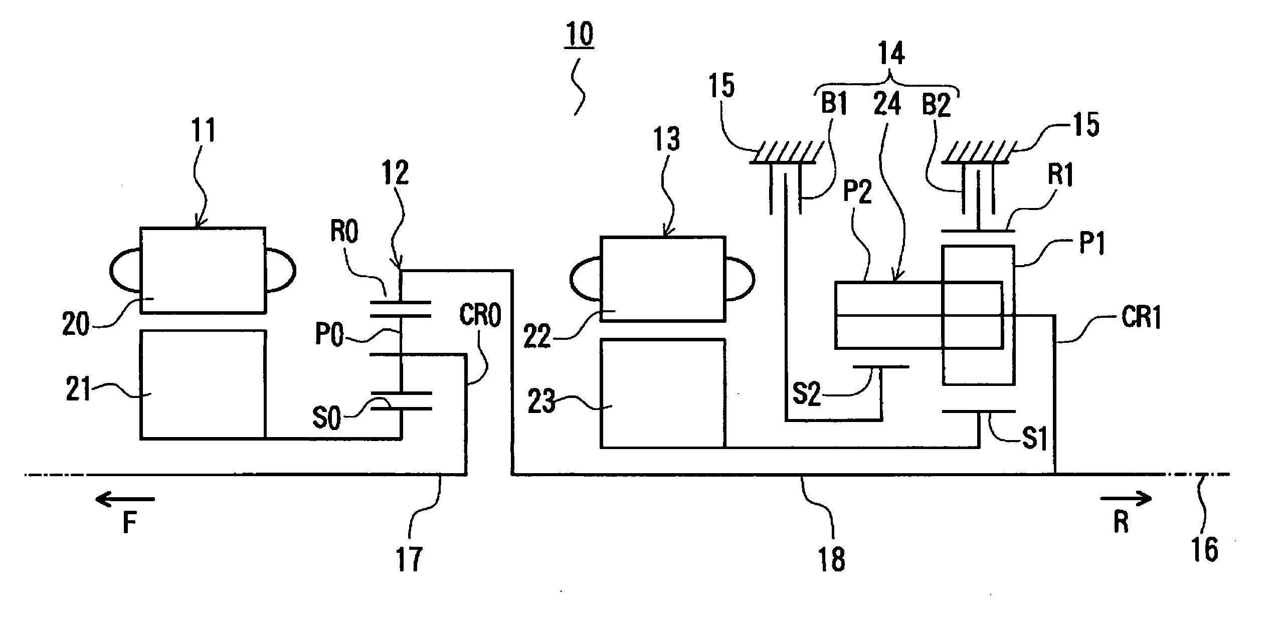
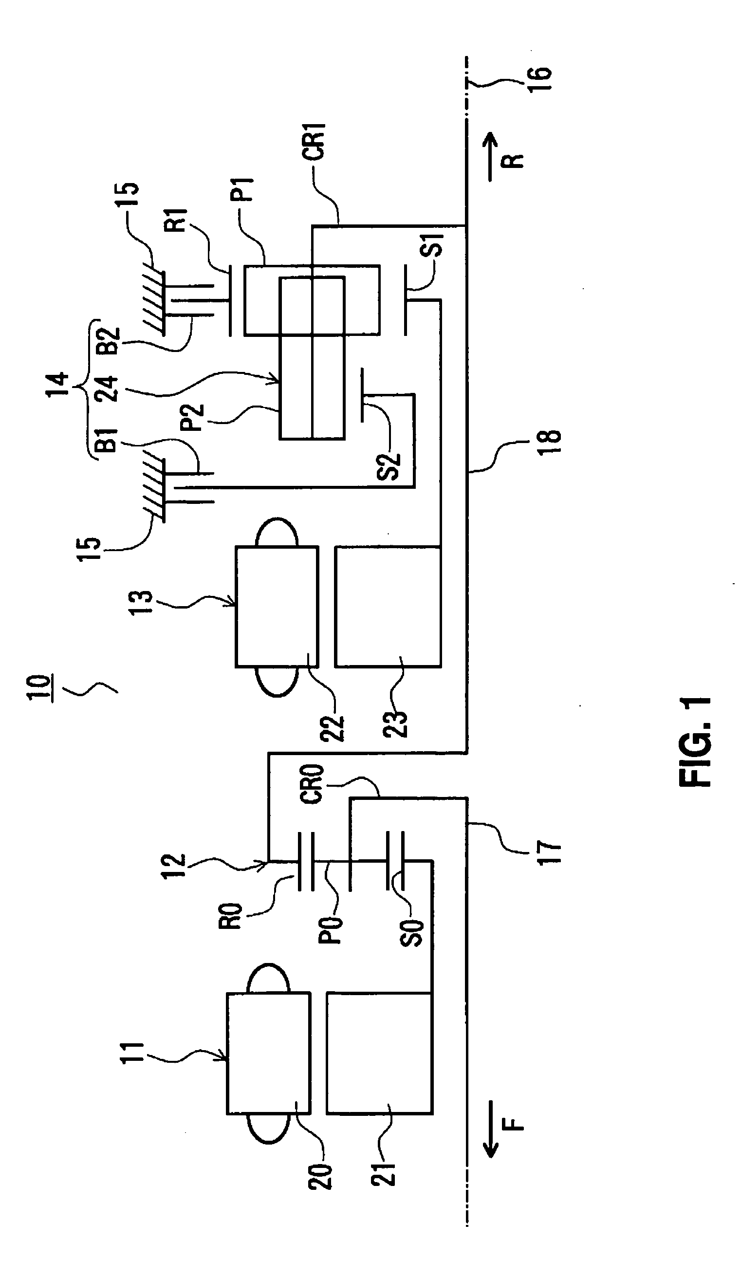
[0024] With reference to the skeleton diagram shown in FIG. 1, an overall structure of a hybrid drive apparatus 10 will be briefly described. In FIG. 1, the direction of an arrow F indicates a forward side (engine side) of a motor vehicle, and the direction of an arrow R indicates a rearward side (differential device side) of the motor vehicle.

[0025] As shown in FIG. 1, the hybrid drive apparatus 10 has a first electric motor 11, a power splitting planetary gear 12, a second electric motor 13, and a speed change apparatus 14 which are disposed in that order from the forward side to the rearward side. These components and the like are contained in a case 15, and are arranged around an axis 16 (the center axis of an input shaft 17 and an output shaft 18). The case 15 has been formed into an integral...


PUM


Abstract

A failsafe hydraulic circuit designed to avoid simultaneous engagement of two friction engagement elements (e.g., clutches, brakes, etc.) incorporated in a speed change apparatus of a motor vehicle or the like. If a first failsafe valve is in the open position state and a first engaging pressure is supplied to a first hydraulic servo via the first failsafe valve, the first engaging pressure is also input to a first oil pressure switch via a second failsafe valve being in the closed position state. Therefore, using the first oil pressure switch, it can be detected that the first engaging pressure is supplied to the first hydraulic servo. Furthermore, if the first engaging pressure is, for example, greater than the set pressure of the first oil pressure switch, this situation can also be detected. Such detections provide confirmation of normal operation of the first failsafe valve and the second failsafe valve.

Description

[0001] The disclosure of Japanese Patent Application No. 2003-371354 filed on Oct. 30, 2003, including the specification, drawings and abstract is incorporated herein by reference in its entirety. BACKGROUND OF THE INVENTION [0002] 1. Field of the Invention [0003] The present invention relates to a failsafe hydraulic circuit designed to avoid simultaneous engagement of two friction engagement elements (e.g., clutches, brakes, etc.) incorporated in, for example, a speed change apparatus of a motor vehicle or the like. [0004] 2. Description of the Related Art [0005] A speed change apparatus installed in a motor vehicle or the like has a plurality of clutches and brakes that are engaged and disengaged on the basis of the engaging pressures supplied to hydraulic servos. Among these clutches and brakes, the clutches and brakes that need to avoid simultaneous engagement are provided with failsafe hydraulic circuits. [0006] A known failsafe hydraulic circuit as mentioned above is equipped ...

Claims


Application Information

Patent Timeline
IPC IPC(8): B60K6/445B60K6/547B60W10/10B60W20/00F15B20/00F16D48/04F16H61/12
CPCF15B20/008F16D48/04F16H2061/1264F16H2061/1224F16H2061/1204F16H61/12F16D2048/0221F16D2048/0236F16D2048/0281F16D2500/3024F16D2500/3058F16H61/4192
Inventor KINUGASA, SEIICHIONODA, MASANORIENOMOTO, KAZUHITOMIURA, KIYOTOMOFUKAYA, NAOYUKIWAKUTA, SATORUADACHI, MASATOSHIMURAKAMI, AKIRA
Owner AISIN AW CO LTD
Why Eureka
Try Eureka