Failsafe hydraulic circuit

a hydraulic circuit and failure-safe technology, applied in mechanical equipment, transportation and packaging, gearing, etc., can solve problems such as the inability to acquire further information

Inactive Publication Date: 2006-10-31
AISIN AW CO LTD +1
View PDF14 Cites 15 Cited by
  • Summary
  • Abstract
  • Description
  • Claims
  • Application Information

AI Technical Summary

Benefits of technology

[0012]Likewise, if the second failsafe valve is in the open position state and the second engaging pressure is supplied to the second hydraulic servo via the second failsafe valve, the second friction engagement element is engaged by the second engaging pressure. In this case, the first failsafe valve is set to the closed position state by the second engaging pressure, so that the first hydraulic servo is not supplied with the first engaging pressure. Therefore, the first friction engagement element is not engaged. Thus, in the failsafe hydraulic circuit, while one of the hydraulic servos is supplied with the engaging pressure via one of the failsafe valves and therefore one of the friction engagement elements is engaged, the other hydraulic servo is not supplied with the engaging pressure via the other failsafe valve, and therefore the other friction engagement element is not engaged. That is, an event where one of the friction engagement elements and the other one are simultaneously engaged is avoided.
[0013]Furthermore, the hydraulic circuit in which when one of the first failsafe valve and the second failsafe valve is in the open position state, the other one of the failsafe valves is set to the closed position state is formed by inputting the oil pressure generated by the oil pressure generator device to the first and second failsafe valves. The first engaging pressure is input to the first oil pressure detector device via the second failsafe valve. The second engaging pressure is input to the second oil pressure detector device via the first failsafe valve. Therefore, the failsafe hydraulic circuit is able to detect whether the operation of the failsafe valves is normal, and is also able to detect the engaging pressure supplied to each hydraulic servo.
[0014]According to a second aspect of the present invention, the engaging pressure adjusted by a first linear solenoid valve and the engaging pressure adjusted by a second linear solenoid valve can be directly supplied to the first failsafe valve and the second failsafe valve, respectively. Therefore, it becomes possible to simplify the overall structure in comparison with, for example, a structure in which a control pressure (signal pressure) is generated by a linear solenoid valve and, on the basis of the control pressure, the pressure adjustment is accomplished by a different valve.
[0016]According to a fourth aspect of the present invention, the oil pressure that linearly corresponds to the engaging pressure supplied to one of the two hydraulic servos can be input to a corresponding one of the two oil pressure detector devices, so that the engaging pressure supplied to the one of the hydraulic servos can be relatively directly detected.
[0017]According to a fifth aspect of the present invention, the two brakes that need to avoid simultaneous engagement can be prevented from simultaneously engaging.
[0018]According to a sixth aspect of the present invention, the two clutches that need to avoid simultaneous engagement can be prevented from simultaneously engaging.

Problems solved by technology

However, the above-described failsafe hydraulic circuit has the following problem.
That is, although the oil pressure switch is able to detect whether the operation of the failsafe valve is normal, it is impossible to acquire further information, for example, information regarding the engaging pressure supplied to the hydraulic servo or the like.

Method used


Image

  • Failsafe hydraulic circuit
  • Failsafe hydraulic circuit
  • Failsafe hydraulic circuit

Examples


Embodiment Construction

[0022]Exemplary embodiments of the present invention will be described hereinafter with reference to the accompanying drawings. In the drawing, like reference numerals and characters are used to denote components or the like which have like structures or carry out like operations. Repeated descriptions of such components or the like are appropriately avoided.

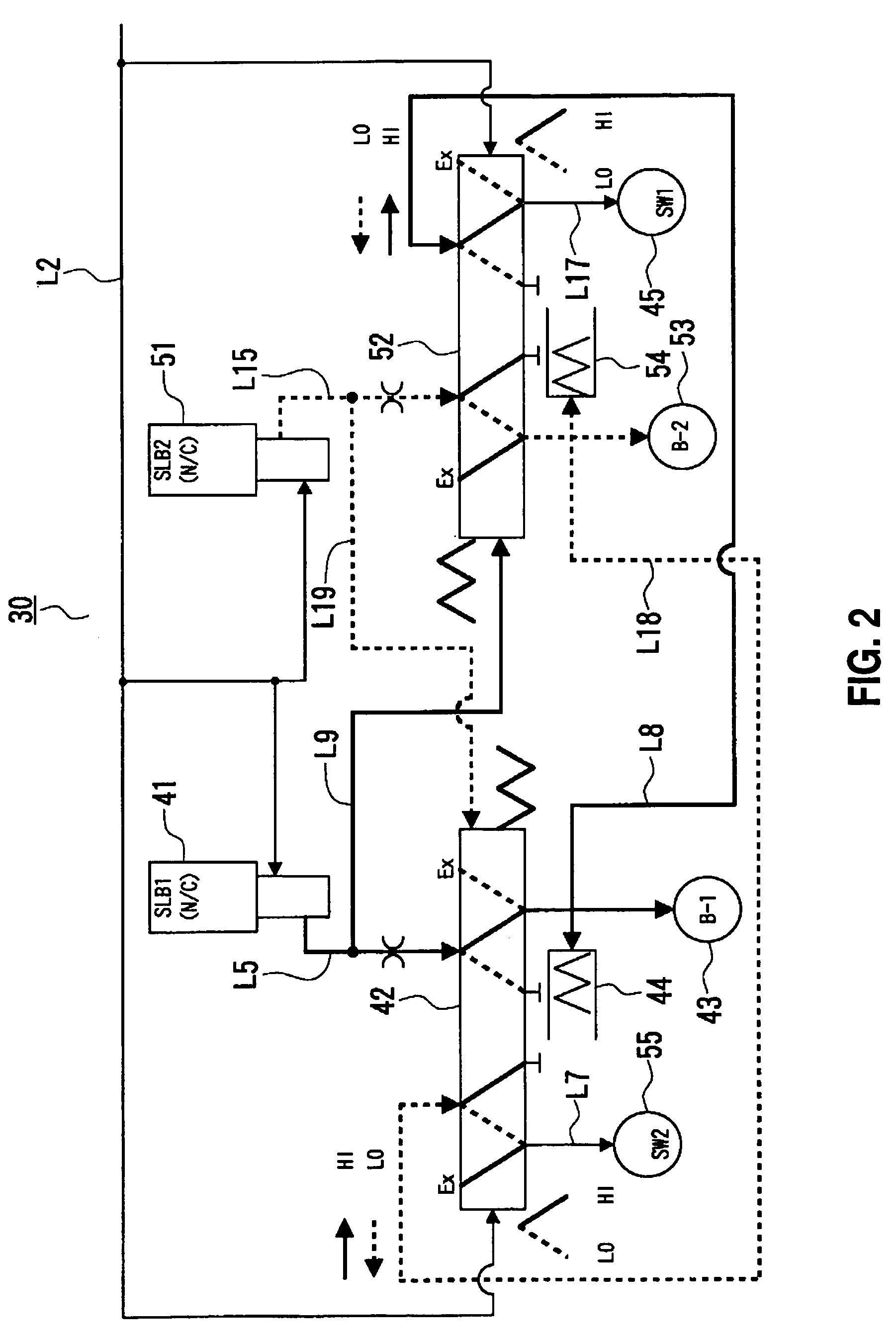
[0023]A failsafe oil passage structure 30 (see FIGS. 2 and 3) in accordance with the present invention is applicable to, for example, a hybrid drive apparatus mounted in a motor vehicle.

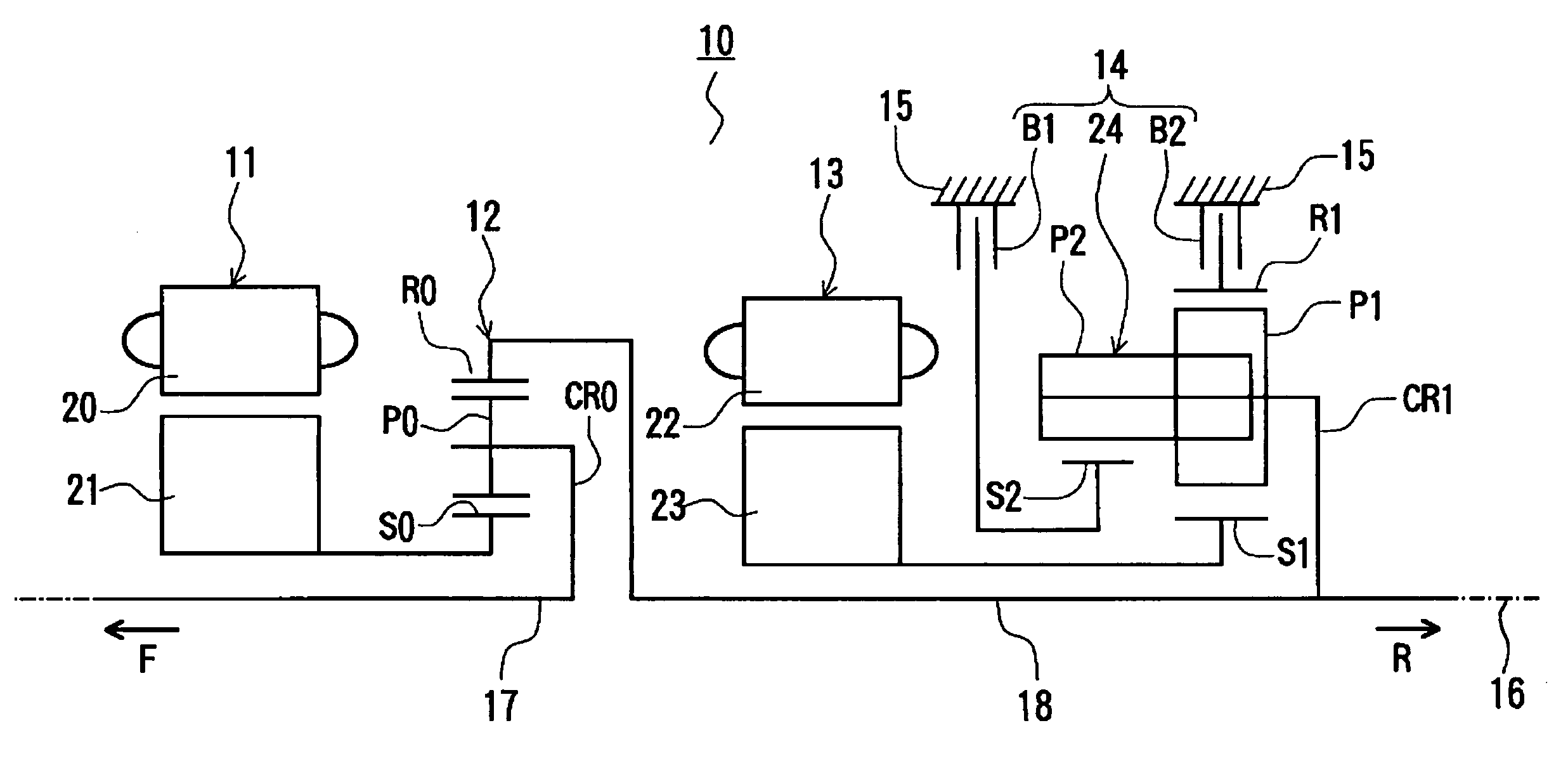
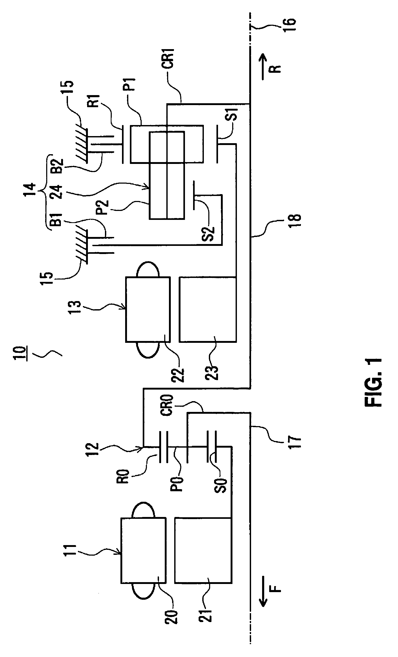
[0024]With reference to the skeleton diagram shown in FIG. 1, an overall structure of a hybrid drive apparatus 10 will be briefly described. In FIG. 1, the direction of an arrow F indicates a forward side (engine side) of a motor vehicle, and the direction of an arrow R indicates a rearward side (differential device side) of the motor vehicle.

[0025]As shown in FIG. 1, the hybrid drive apparatus 10 has a first electric motor 11, a power splitting ...


PUM


Abstract

A failsafe hydraulic circuit designed to avoid simultaneous engagement of two friction engagement elements (e.g., clutches, brakes, etc.) incorporated in a speed change apparatus of a motor vehicle or the like. If a first failsafe valve is in the open position state and a first engaging pressure is supplied to a first hydraulic servo via the first failsafe valve, the first engaging pressure is also input to a first oil pressure switch via a second failsafe valve being in the closed position state. Therefore, using the first oil pressure switch, it can be detected that the first engaging pressure is supplied to the first hydraulic servo. Furthermore, if the first engaging pressure is, for example, greater than the set pressure of the first oil pressure switch, this situation can also be detected. Such detections provide confirmation of normal operation of the first failsafe valve and the second failsafe valve.

Description

BACKGROUND OF THE INVENTION[0001]The disclosure of Japanese Patent Application No. 2003-371354 filed on Oct. 30, 2003, including the specification, drawings and abstract is incorporated herein by reference in its entirety.[0002]1. Field of the Invention[0003]The present invention relates to a failsafe hydraulic circuit designed to avoid simultaneous engagement of two friction engagement elements (e.g., clutches, brakes, etc.) incorporated in, for example, a speed change apparatus of a motor vehicle or the like.[0004]2. Description of the Related Art[0005]A speed change apparatus installed in a motor vehicle or the like has a plurality of clutches and brakes that are engaged and disengaged on the basis of the engaging pressures supplied to hydraulic servos. Among these clutches and brakes, the clutches and brakes that need to avoid simultaneous engagement are provided with failsafe hydraulic circuits.[0006]A known failsafe hydraulic circuit as mentioned above is equipped with a fails...

Claims


Application Information

Patent Timeline
Patent Type & Authority Patents(United States)
IPC IPC(8): F16H3/72F16H31/00B60K6/445B60K6/547B60W10/10B60W20/00F15B20/00F16D48/04F16H61/12
CPCF15B20/008F16D48/04F16H61/12F16H2061/1224F16H2061/1204F16H2061/1264F16D2048/0221F16D2048/0236F16D2048/0281F16D2500/3024F16D2500/3058F16H61/4192
Inventor KINUGASA, SEIICHIONODA, MASANORIENOMOTO, KAZUHITOMIURA, KIYOTOMOFUKAYA, NAOYUKIWAKUTA, SATORUADACHI, MASATOSHIMURAKAMI, AKIRA
Owner AISIN AW CO LTD
Why Eureka
Try Eureka