Electronic signal amplifier and method and article for determining the gain of such an amplifier

a technology of amplifier and amplifier, applied in the field of electronic signal amplifier, can solve the problem of high production cost of amplifier, and achieve the effect of reducing production cos

Active Publication Date: 2005-09-01
STMICROELECTRONICS SRL
View PDF2 Cites 4 Cited by
  • Summary
  • Abstract
  • Description
  • Claims
  • Application Information

AI Technical Summary

Benefits of technology

[0016] One embodiment of the present invention pro...

Problems solved by technology

In order to obtain an amplifier with a high output current capability, there must be a sufficiently large number of amplification cells N. Usua...

Method used


Image

  • Electronic signal amplifier and method and article for determining the gain of such an amplifier
  • Electronic signal amplifier and method and article for determining the gain of such an amplifier
  • Electronic signal amplifier and method and article for determining the gain of such an amplifier

Examples


Embodiment Construction

[0060] Identical reference numbers used over several figures correspond to identical elements, or elements that have analogous functions, unless the context indicates otherwise.

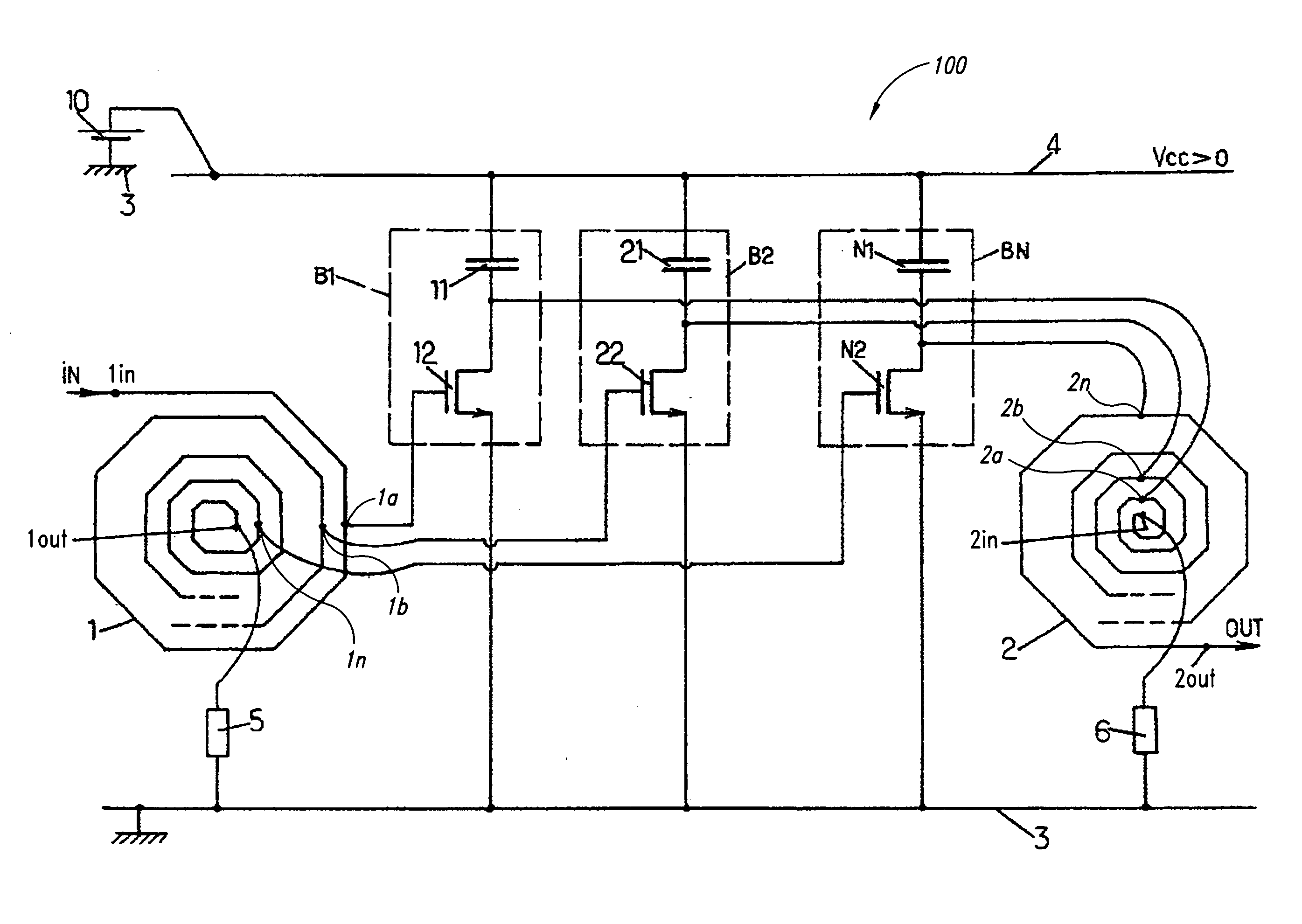
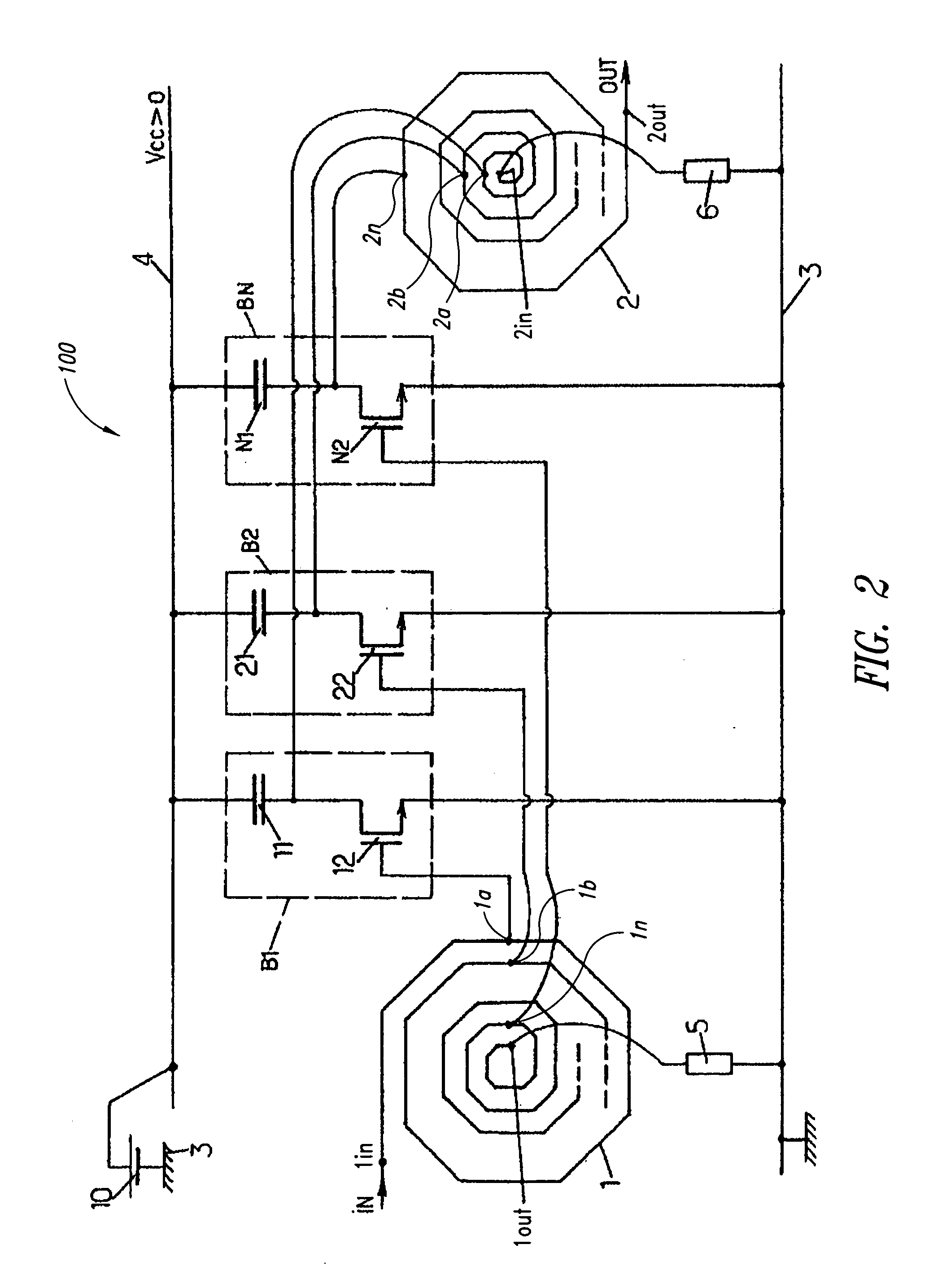
[0061] According to the circuit diagram in FIG. 2, an electronic signal amplifier 100 comprises two inductors 1 and 2, designated respectively as input inductor and output inductor. Each of the inductors 1 and 2 can be formed by a plane, spiral-wound trace comprising (N+1) more or less concentric turns. Each inductor 1, 2 comprises two nodes or end terminals located respectively on the periphery and in the centre of the corresponding inductor trace, and N intermediate terminals located between the end terminals along the trace. The end terminal located on the periphery of the trace of the inductor 1 is the input node or terminal of the inductor 1; it has the reference 1in. The end terminal located in the centre of the trace of the inductor 1 is the output node or terminal of the inductor 1, with the referenc...


PUM


Abstract

An embodiment of an electronic signal amplifier comprises a power source, an input inductor, an output inductor and one or more branches connected in parallel between the terminals of the power source. Each branch comprises a transistor having a control electrode connected to an intermediate terminal of the input inductor, a first main electrode connected to a first terminal of the power source, and a second main electrode connected to a second terminal of the power source via a capacitor. The second main electrode of each transistor of a branch is also connected to an intermediate terminal of the output inductor.

Description

BACKGROUND OF THE INVENTION [0001] 1. Field of the Invention [0002] The present disclosure relates to an electronic signal amplifier. It also relates to an article for determining the gain of such an amplifier. [0003] 2. Description of the Related Art [0004] An amplifier corresponding to the circuit diagram in FIG. 1 is known to those skilled in the art. Such an amplifier comprises a given number N of quadrupolar amplification cells referenced C1, C2, . . . , CN connected in series, where N is an integer greater than or equal to unity. By reason of this structure, the amplifier is classed as a “distributed amplifier”. It additionally comprises a power source 10 having a ground node or terminal 3 and a positive supply node or terminal 4. [0005] The cell C1 comprises a capacitor 11 of capacitance Γ1, a transistor 12, for example of the n-MOS type, and two inductors 13 and 14 of respective values L13 and L14. The source of the transistor 12 is connected to the terminal 3, and the drain...

Claims


Application Information

Patent Timeline
IPC IPC(8): H03F1/18H03F3/60
CPCH03F1/18H03F2200/372H03F2200/294H03F3/607
Inventor BELOT, DIDIER
Owner STMICROELECTRONICS SRL
Why Eureka
Try Eureka