Image-forming apparatus and sheet discharge tray
a discharge tray and image-forming technology, applied in the direction of electrographic process, instruments, transportation and packaging, etc., can solve the problems of discharged sheet easily curled, adversely affecting the stacking state of the sheet-receiving unit, and aiming to solve the problem
- Summary
- Abstract
- Description
- Claims
- Application Information
AI Technical Summary
Benefits of technology
Problems solved by technology
Method used
Image
Examples
first embodiment
(First Embodiment)
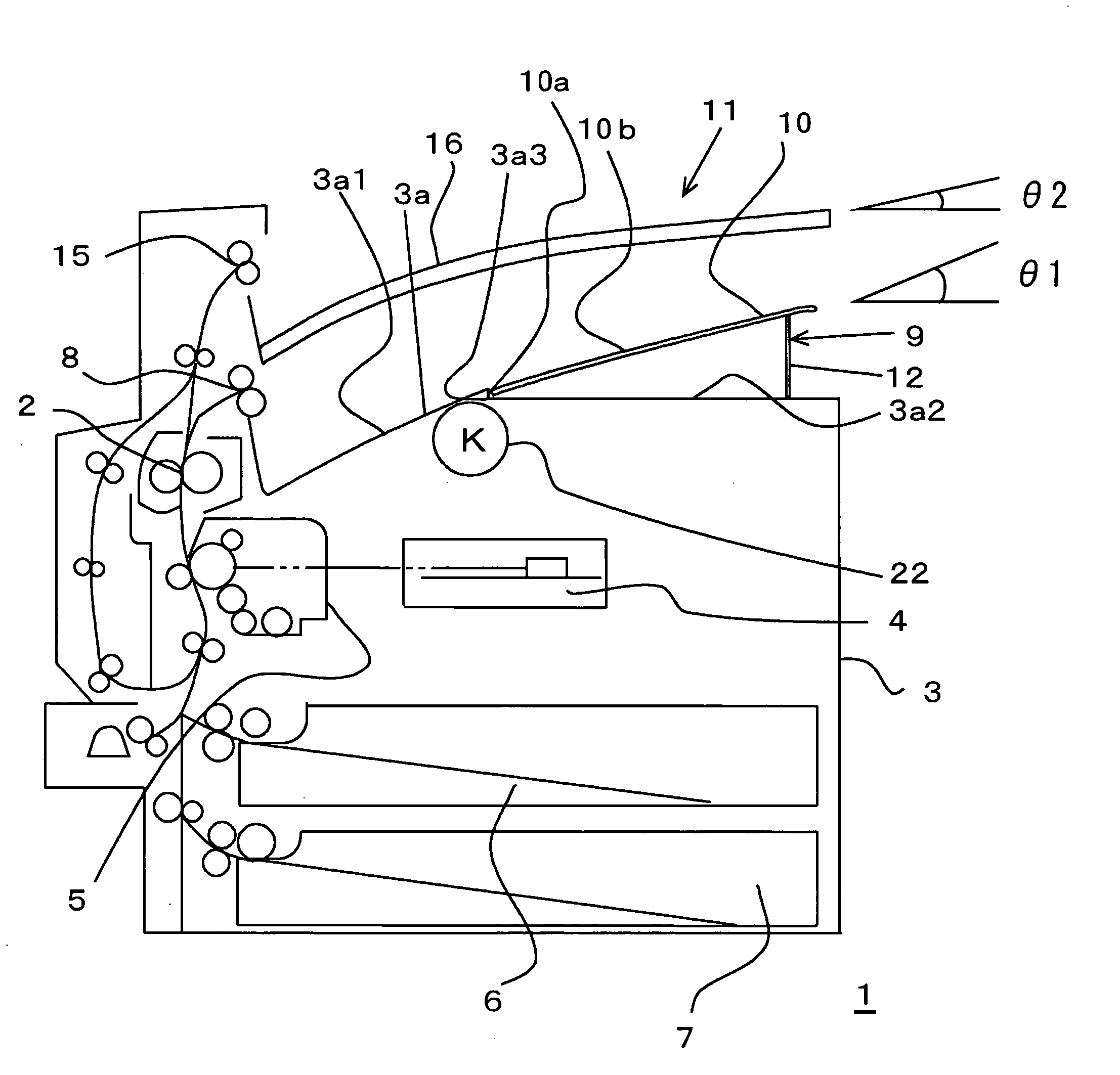
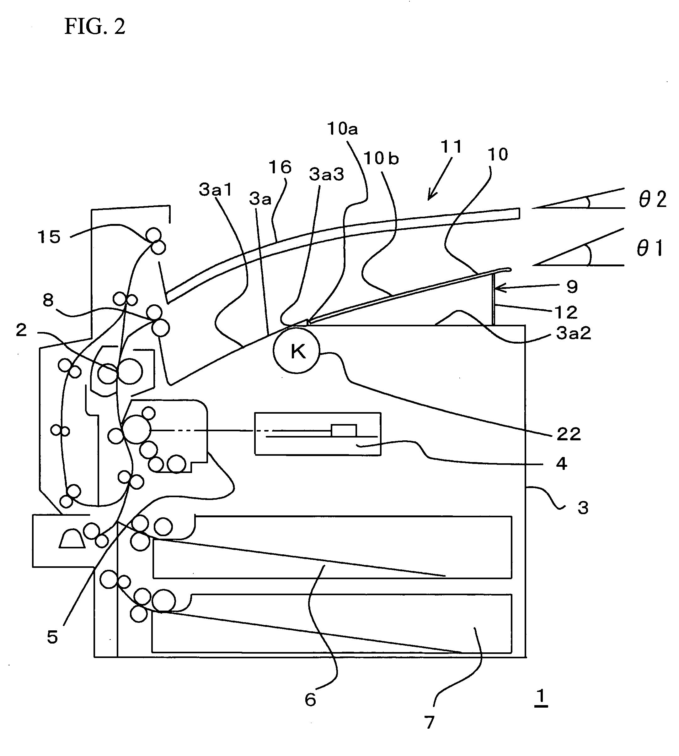
[0040] A description will be given of an image-forming apparatus 1 in accordance with the present invention, with reference to FIGS. 2 through 5. FIG. 2 schematically illustrates the image-forming apparatus 1 having two sheet-receiving units in a two-layered structure. FIG. 3 schematically illustrates the image-forming apparatus 1 having three sheet-receiving units in a three-layered structure. FIG. 4 is an exploded perspective view of a first receiving unit provided in an undermost layer. An image-reading unit, not shown, is provided above the image-forming unit.
[0041] A fixing unit 2 is arranged in a container box 3. Additionally, the container box 3 includes a photolithography machine 4, an image-forming unit 5, sheet feeding trays 6 and 7, a first discharge roller 8, and a black (K) toner cartridge 22. In the container box 3, a top board 3a forms a first sheet-receiving unit 9, as shown in FIG. 2. The top board 3a includes a slope portion 3a1, a plane surface ...
second embodiment
(Second Embodiment)
[0058] Next, a description will be given of a second embodiment of the present invention. The image-forming apparatus 1 includes the variable tray 10 supported by the stopper 12 in accordance with the first embodiment of the present invention. However, the variable tray 10 is elastically supported by an elastic member between the variable tray 10 and the plane surface portion 3a2 in accordance with the second embodiment of the present invention.
[0059] Referring to FIG. 10, a torsion spring 27 may be used for the elastic member. Referring to FIG. 11, a compression spring 28 may be used. The variable tray 10 may be supported by both the elastic member and the stopper 12.
[0060] As shown in FIGS. 2 and 3, the second sheet-receiving unit 11 is provided above the first sheet-receiving unit 9. Therefore, a gap is narrow between the first sheet-receiving unit 9 and the second sheet-receiving unit 11. However, in the case where the above-mentioned elastic member is provi...
third embodiment
(Third Embodiment)
[0062] Next, a description will be given of a third embodiment of the present invention. As shown in FIG. 4, the image-forming apparatus 1 includes the variable tray 10 having the concave slope 10d on the side of the sheet discharge direction end point. However, referring to FIG. 12, instead of the concave slope 10d, a cutout portion 10c is included in accordance with the third embodiment of the present invention. The stopper 12 has a shape different from that of the first embodiment of the present invention.
[0063] With the above-mentioned configuration, it is easy to inset the hand into a space between the plane surface portion 3a2 and the variable tray 10, and it is easy to take out the sheet.
PUM
 Abstract
Description
Claims
Application Information
 - R&D
- Intellectual Property
- Life Sciences
- Materials
- Tech Scout
- Unparalleled Data Quality
- Higher Quality Content
- 60% Fewer Hallucinations
Browse by: Latest US Patents, China's latest patents, Technical Efficacy Thesaurus, Application Domain, Technology Topic, Popular Technical Reports.
© 2025 PatSnap. All rights reserved.Legal|Privacy policy|Modern Slavery Act Transparency Statement|Sitemap|About US| Contact US: help@patsnap.com


