Image-forming apparatus and multiple sheet curl correcting sheet-receiving units

a technology of image-forming apparatus and discharge tray, which is applied in the direction of electrographic process, instruments, transportation and packaging, etc., can solve the problems of discharged sheet easily curled, adversely affected storage state of sheet-receiving unit, and the intention of solving the problem

Inactive Publication Date: 2010-05-04
FUJIFILM BUSINESS INNOVATION CORP
View PDF10 Cites 9 Cited by
  • Summary
  • Abstract
  • Description
  • Claims
  • Application Information

AI Technical Summary

Benefits of technology

[0016]The present invention has been made in view of the above circumstances and provides an image-forming apparatus that can prevent a sheet of paper having passed through a fixing unit from getting curled and prevent a stacking state of discharged sheets from degrading.

Problems solved by technology

As described above, if the discharged sheet is curled, a stacking state on the sheet-receiving unit will adversely be affected.
However, the proposals of the Documents 1 through 3 are not made to solve the above-mentioned problem, that is, the discharged sheet easily gets curled.
Proposals made by Documents 1 through 3 do not intend to solve the problem of the curled discharge sheet.

Method used


Image

  • Image-forming apparatus and multiple sheet curl correcting sheet-receiving units
  • Image-forming apparatus and multiple sheet curl correcting sheet-receiving units
  • Image-forming apparatus and multiple sheet curl correcting sheet-receiving units

Examples


first embodiment

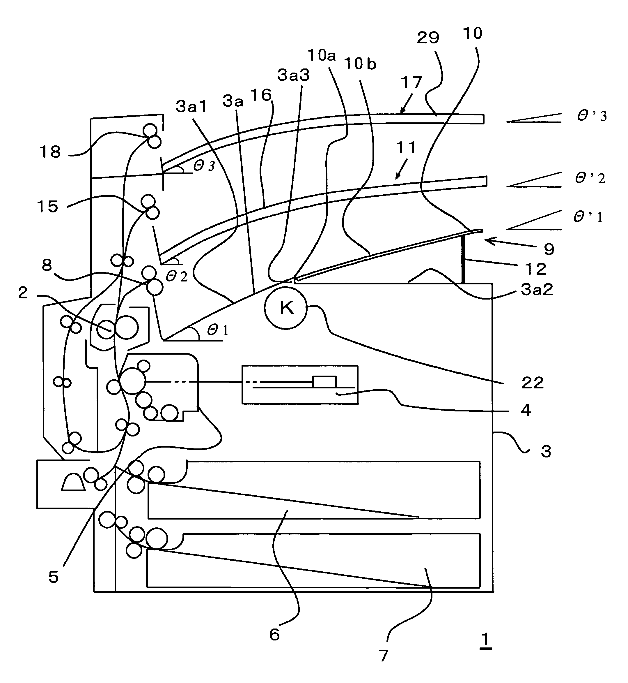
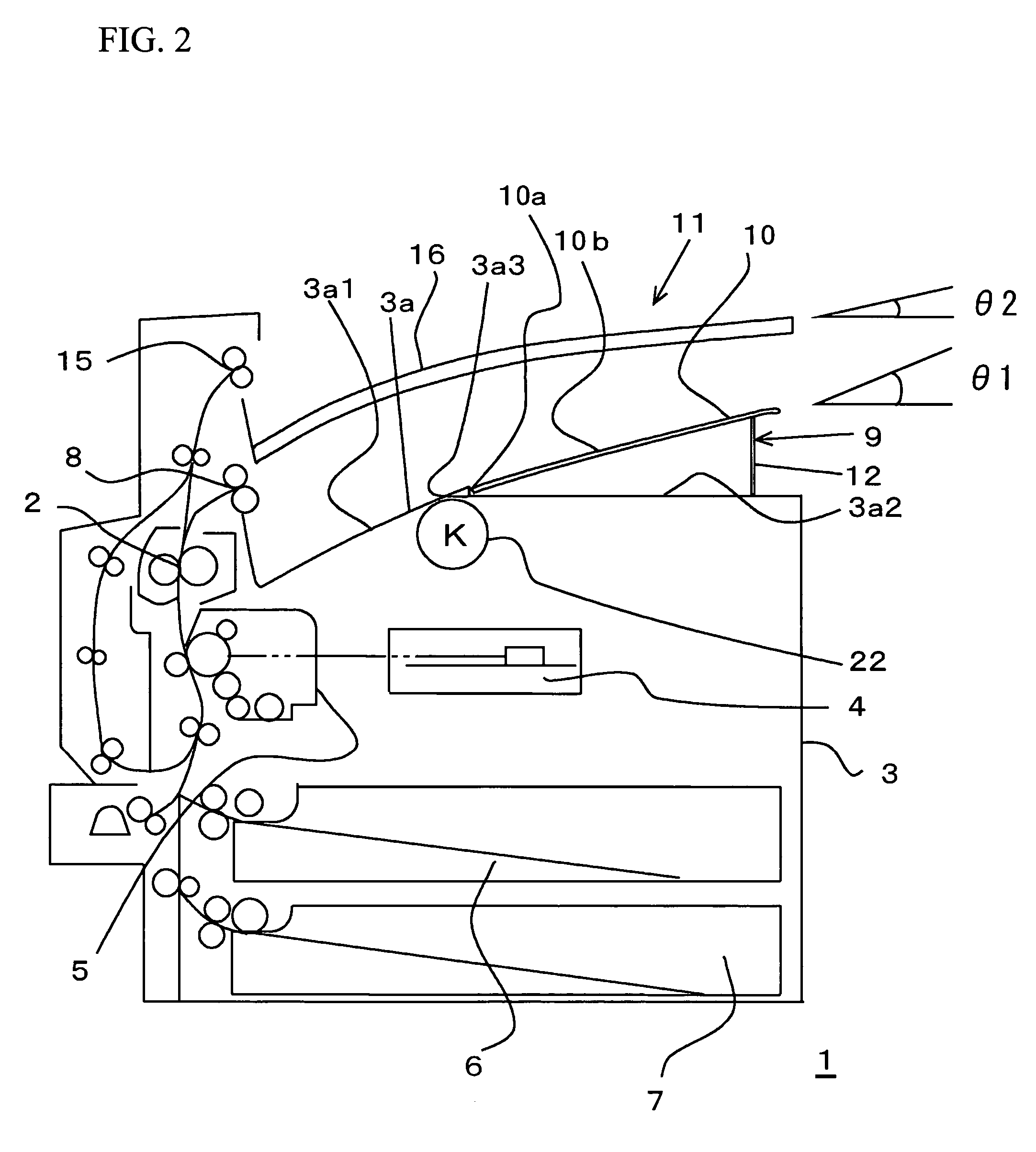
[0040]A description will be given of an image-forming apparatus 1 in accordance with the present invention, with reference to FIGS. 2 through 5. FIG. 2 schematically illustrates the image-forming apparatus 1 having two sheet-receiving units in a two-layered structure. FIG. 3 schematically illustrates the image-forming apparatus 1 having three sheet-receiving units in a three-layered structure. FIG. 4 is an exploded perspective view of a first receiving unit provided in an undermost layer. An image-reading unit, not shown, is provided above the image-forming unit.

[0041]A fixing unit 2 is arranged in a container box 3. Additionally, the container box 3 includes a photolithography machine 4, an image-forming unit 5, sheet feeding trays 6 and 7, a first discharge roller 8, and a black (K) toner cartridge 22. In the container box 3, a top board 3a forms a first sheet-receiving unit 9, as shown in FIG. 2. The top board 3a includes a slope portion 3a1, a plane surface portion 3a2, and a st...

second embodiment

[0058]Next, a description will be given of a second embodiment of the present invention. The image-forming apparatus 1 includes the variable tray 10 supported by the stopper 12 in accordance with the first embodiment of the present invention. However, the variable tray 10 is elastically supported by an elastic member between the variable tray 10 and the plane surface portion 3a2 in accordance with the second embodiment of the present invention.

[0059]Referring to FIG. 10, a torsion spring 27 may be used for the elastic member. Referring to FIG. 11, a compression spring 28 may be used. The variable tray 10 may be supported by both the elastic member and the stopper 12.

[0060]As shown in FIGS. 2 and 3, the second sheet-receiving unit 11 is provided above the first sheet-receiving unit 9. Therefore, a gap is narrow between the first sheet-receiving unit 9 and the second sheet-receiving unit 11. However, in the case where the above-mentioned elastic member is provided, multiple sheets are...

third embodiment

[0062]Next, a description will be given of a third embodiment of the present invention. As shown in FIG. 4, the image-forming apparatus 1 includes the variable tray 10 having the concave slope 10d on the side of the sheet discharge direction end point. However, referring to FIG. 12, instead of the concave slope 10d, a cutout portion 10c is included in accordance with the third embodiment of the present invention. The stopper 12 has a shape different from that of the first embodiment of the present invention.

[0063]With the above-mentioned configuration, it is easy to inset the hand into a space between the plane surface portion 3a2 and the variable tray 10, and it is easy to take out the sheet.


PUM


Abstract

An image-forming apparatus includes multiple sheet discharge trays arranged on a downstream of a fixing unit in a layer structure, and multiple sheet-receiving units provided corresponding to the multiple sheet discharge trays arranged in the layer structure. Each of the sheet-receiving units respectively includes a climbing slope from a sheet discharge direction start point to a sheet discharge direction end point, and an angle of the climbing slope of a sheet-receiving unit is close to plane, as the sheet-receiving unit is arranged on a further downstream. It is thus possible to provide the image-forming apparatus in which discharged sheets of paper are not piled up on the sheet-receiving unit in a curled state or the discharged sheet does not push out the sheet piled on the sheet-receiving unit.

Description

BACKGROUND OF THE INVENTION[0001]1. Field of the Invention[0002]This invention relates to image-forming apparatuses, in particular, to a sheet discharge unit or a sheet discharge tray provided for loading a printed sheet of paper.[0003]2. Description of the Related Art[0004]Conventionally, an image-reading unit (scanner) and an image-forming unit are separately arranged above and below. The image-reading unit (scanner) is arranged above the image-forming unit having an image-fixing unit and the like. The image-reading unit (scanner) and an image-forming unit are separately arranged so that the sheet discharge tray may not protrude from side faces of the image-forming unit. The sheet discharge tray is used for loading printed sheets of paper. Thus arranged image-reading unit and the image-forming unit forms a space for providing the sheet discharge unit.[0005]Recently, with the background of advancements in the complex capabilities of the image-forming apparatus, the place where the ...

Claims


Application Information

Patent Timeline
Patent Type & Authority Patents(United States)
IPC IPC(8): G03G15/00
CPCG03G15/00B65H2405/1116B65H2801/06G03G15/6552G03G2215/00421
Inventor SUZUKI, SHIROH
Owner FUJIFILM BUSINESS INNOVATION CORP
Why Eureka
Try Eureka