Mounting platform for construction stilt

a technology for building platforms and stilts, applied in the field of stilts, can solve the problems of increased instability, lack of control of the stilt, and a certain amount of user instability

Inactive Publication Date: 2005-09-15
SIMMONS JOSEPH
View PDF9 Cites 9 Cited by
  • Summary
  • Abstract
  • Description
  • Claims
  • Application Information

AI Technical Summary

Benefits of technology

[0011] The present invention generally relates to stilts, and more specifically relates to foot support structures for use with stilts. An example foot support structure according to principles of the present invention includes a foot platform and side walls that extend along opposing sides and a heel portion of the foot platform in a direction generally perpendicular to a primary top surface of the foot platform. Adjustable straps of the foot support structure are secured to the side walls and may be adjusted to different positions along the side walls in the longitudinal direction of the foot support structure. The side walls also provide lateral and longitudinal support of a user's foot supported by the foot support structure.

Problems solved by technology

Typically, the foot platform 212 is narrower and sometimes shorter than the footwear of the user, which results in a certain amount of instability for the user.
This lack of lateral support in combination with a foot platform that is more narrow than the user's footwear results in additional instability and lack of control of the stilt.
Even if the foot platform 212 were wider than the user's footwear, the lack of lateral support inherent in the pliable straps and the connection of the straps across the top surface of the platform are significant drawbacks.
Another drawback of foot support structure 200 is that there is no adjustability provided to optimize the position of the straps 218, 220 relative to the user's foot.
A still further disadvantage of known foot support structures is that the materials used for the front and rear straps are highly susceptible to wear under these conditions, and the design of the straps provides little comfort for a user.
Since footwear tread is typically abrasive, especially along edges of the footwear, the straps are often quickly worn in these contact areas.
Strap failure results in additional strap replacement costs for the user.
Further, the narrow, thin straps 218, 220 provide a minimum contact surface area with the user's foot, which results in the strap constricting the user's foot in an often uncomfortable way when the strap is tightened sufficiently to provide some control of the stilt by the user.

Method used


Image

  • Mounting platform for construction stilt
  • Mounting platform for construction stilt
  • Mounting platform for construction stilt

Examples


Embodiment Construction

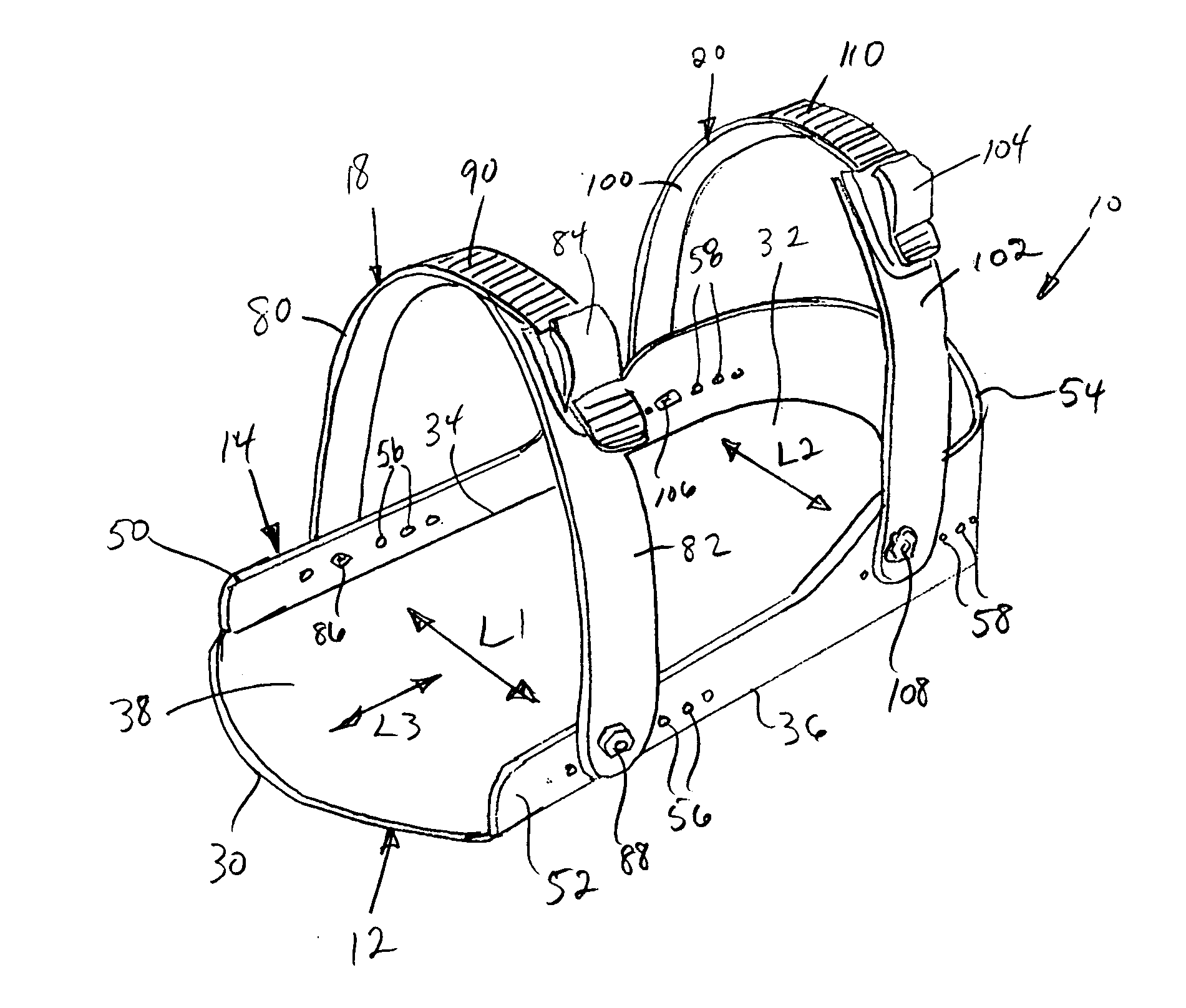
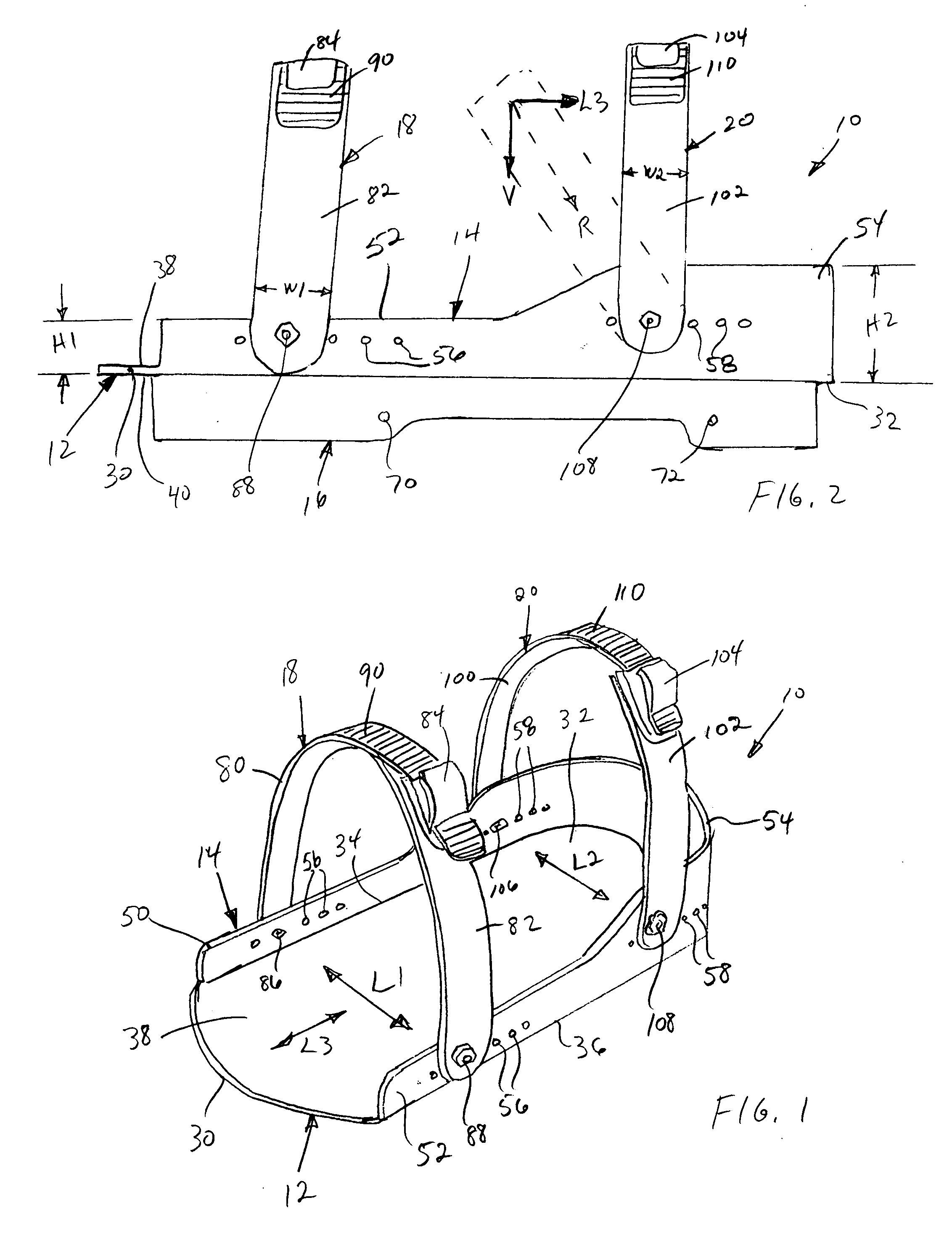
[0027] The present invention generally relates to stilts, and more specifically relates to foot support structures for use with stilts. An example foot support structure according to principles of the present invention includes a foot platform and side walls that extend along opposing sides and a heel portion of the foot platform in a direction generally perpendicular to a primary top surface of the foot platform. Adjustable straps of the foot support structure are secured to the side wall at opposing sides of the foot platform and may be adjusted to different positions along the side walls in the longitudinal direction of the foot support structure. The side walls provide lateral and longitudinal support of a user's foot supported by the foot support structure.

[0028] As used herein the term “strap” may be referred to as an adjustable retaining member and is intended to be a band, plate, or loop of metal for binding objects together or for clamping an object in position, and may fu...


PUM


Abstract

A foot support structure of the type used with a stilt includes a foot platform, a side wall, and first and second adjustable retaining members. The foot platform includes opposed first and second primary surfaces, a toe end, a heel end, and first and second sides. The side wall extends in a substantially normal direction from the first primary surface and extends along at least a portion of the first and second sides and a portion of the heel end of the base member. The front and rear adjustable retaining members are coupled to the side wall and extend between the first and second sides of the foot platform.

Description

BACKGROUND OF THE INVENTION [0001] 1.Field of the Invention [0002] The present invention generally relates to stilts, and more specifically relates to foot support structures for stilts. [0003] 2.Related Art [0004] Stilts usually include a pole member and a foot stand or strap that is secured to the pole that a user positions their foot upon to elevate the user above the ground in walking. Stilts are used for entertainment purposed by circus clowns and the like, and are also used by construction workers and others who require additional height to perform their tasks. For example, construction workers who finish wallboard walls using tape and joint compound often use stilts to elevate themselves to a higher position to work on the upper portion of the walls and the ceiling of a room. Stilts not only provide an elevated working position, but also provide mobility for the worker at the elevated position. [0005] Stilts typically include some type of foot support structure that the user ...

Claims


Application Information

Patent Timeline
Patent Type & Authority Applications(United States)
IPC IPC(8): A63B25/00
CPCA63B25/00
Inventor SIMMONS, JOSEPH
Owner SIMMONS JOSEPH
Why Eureka
Try Eureka