Accumulator structure

Inactive Publication Date: 2005-09-22
FUJI JUKOGYO KK
View PDF5 Cites 5 Cited by
  • Summary
  • Abstract
  • Description
  • Claims
  • Application Information

AI Technical Summary

Benefits of technology

[0009] The present invention is in view of the above-described disadvantages, and it is an object of the present invention to provide an accumulator structure that can be installed three-dimensionally with bending flexibility while the flat arrangement of the accumulator structure is maintained and a protection ability and an impact absorbing capability is maintained.
[0019] The accumulator structure according to the present invention can be installed three-dimensionally with bending flexibility while the flat arrangement of the accumulator structure is maintained and a protection ability and an impact absorbing capability is maintained.

Problems solved by technology

Since the package case is soft, the tension applied to the cells by the case cannot be large.
However, in the laminate accumulator of JP-A-2001-256938, for a restriction of the half-shell shape of the case, it is very difficult to flexibly installing the laminate accumulator in the limited space.
Further, in the laminate accumulator of JP-A-2003-162989, since the resin is filled between the support member and the unit cells and a prescribed space is necessary between the support member and the unit cells, a space that the laminate accumulator can be installed thereto is restricted, and it is difficult to install the laminate accumulator in various shapes.

Method used


Image

  • Accumulator structure
  • Accumulator structure
  • Accumulator structure

Examples


first embodiment

[0065] In the first embodiment, the module having unit cells in a common plane is reinforced by a string-shaped member and formed as a package.

[0066] The module package 20 shown in FIG. 9 includes four strip-shaped reinforcement members 21a, 21b, 21c, and 21d as diagonally shaded in FIG. 9 that are attached to the module 5 between the electrode terminals arranged in the row-direction alternately at the front surface side and the back surface side. The reinforcement members 21a to 21d are made of an insulator tape such as fabric, leather, and resin, attached through an adhesive or the like, and suspended, so that the reinforcement and insulation between the electrode terminals can effectively be carried out while the bending flexibility is secured.

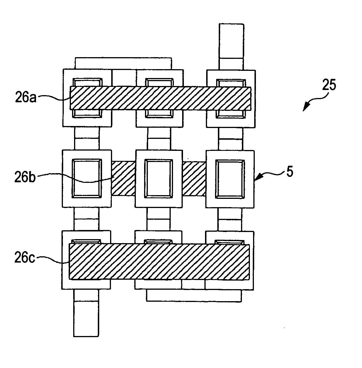
[0067] The module package shown in FIG. 10 is produced by providing the module 5 with three strip-shaped reinforcement members 26a, 26b, and 26c bendably suspended between the accumulator cells 1 as unit cells (flat accumulators) on a row-...

second embodiment

[0077] In the second embodiment, the positional relation between the cells in the module is forcibly maintained by the function of the case member, so that the unit cells can surely be prevented from being shifting to one side by impacts or by its own weight. Consequently, the electrode terminals can be prevented from contacting each other and impacts can be absorbed.

[0078] Now, a third embodiment of the present invention will be described. FIGS. 20 to 24 are related to the third embodiment of the invention. FIG. 20 shows a module package using a grid frame, FIG. 21 is a view seen in the direction of the arrow XXI in FIG. 20, FIG. 22 shows another example of the grid frame, FIG. 23 is a view seen in the direction of the arrow XXIII in FIG. 22, and FIG. 24 shows an example that grid frames are partly provided.

third embodiment

[0079] In the third embodiment, the module having unit cells in a common plane is reinforced using the grid frame as a frame member corresponding to a flat alignment structure of the unit cells.

[0080] The module package 50 shown in FIG. 20 is produced using a plate shaped grid frame 51 corresponding to the matrix arrangement of the unit cells in the module. The grid frame 51 may be made of wood, resin, or a metal material such as aluminum (with an insulating film if necessary), and individually surrounds each of the unit cells (flat accumulators).

[0081] In this case, as shown in FIG. 21 (as seen in the direction of the arrow XXI in FIG. 20), a pair of frames 51a and 51b are desirably used as the frame 51 for each module, so that the module can be held between the front surface side and the back surface side and the unit cells 1 (accumulator cells 1) can be held as they are pressed between the front surface side and the back surface side. In this way, the accumulator structure of th...


PUM


Abstract

An accumulator structure includes a module having a plurality of flat accumulators flatly disposed in a common plane, and the flat accumulators are electrically connected with each other via electrode terminals. Strip-shaped reinforcement members are attached alternately at a front surface side and a back surface side of the module between the electrode terminals. Thereby, a reinforcement and insulation between the electrode terminals can effectively be carried out while a flat structure of the accumulator structure is maintained and bending flexibility is secured, and the accumulator structure can be adjusted to a third-dimensional installment shape.

Description

[0001] This application claims foreign priority based on Japanese patent application No. JP-2004-081569, filed on Mar. 19, 2004, the contents of which is incorporated herein by reference. BACKGROUND OF THE INVENTION [0002] The present invention relates to an accumulator structure in which a plurality of flat accumulators are flatly disposed in a common plane and electrically connected with each other. [0003] In recent years, accumulators including rechargeable batteries such as lithium ion batteries and electrochemical capacitors such as electric double layer capacitors become more compact and lightweight and become to have higher energy density. These accumulators have actively been used as power sources for portable information communication equipments, electric automobiles or hybrid electric automobiles. [0004] In particular, a laminate accumulator comprising: a package case made of a laminated sheet produced by coating both surfaces of a metal layer with resin layers; and genera...

Claims


Application Information

Patent Timeline
IPC IPC(8): H01M6/42H01M6/46H01M50/119H01M50/121H01M50/124H01M50/51H01M50/512
CPCH01M2/0275H01M6/46H01M6/425H01M2/204Y02P70/50H01M50/51H01M50/512H01M50/119H01M50/121H01M50/124H01M50/20H01M50/50
Inventor SAKURAI
Owner FUJI JUKOGYO KK
Why Eureka
Try Eureka