

High throughput flash purification stand and cartridge
- Summary
- Abstract
- Description
- Claims
- Application Information
AI Technical Summary
Benefits of technology
Problems solved by technology
Method used
Image

Examples
first embodiment
[0082] As shown in FIGS. 18 and 20, each end cap 613 of the cartridge 601 comprises a generally cylindric body 625 having an inner face 629 that contacts the frit 621, an external axial surface 633 that is received in the tube 605, and an outer face 637 defining an external end of the cartridge. A central flow passage, generally designated 641 passes through the end cap 613 between the outer face 637 and the inner face 629 to allow fluid flow through the end cap into or out of the tube 605. The central flow passage 641 is substantially similar to the central flow passage 277 of the cartridge 7 in that the central flow passage is designed to allow a sealingly secure fluid connection between the end cap 613 and any suitable device (e.g., stand 1, coupler 329, or sample holder 423) having a male luer fitting. The central flow passage 641 opens to radial grooves 645 on the inner face 629 of the end cap 613 that facilitate a uniform flow distribution of solvent at the inlet end of the ca...
third embodiment
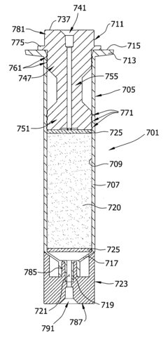
[0089] the chromatography cartridge of the present invention, generally designated 701, is shown in FIGS. 22-25. This embodiment 701 is similar to the previous embodiments in that the cartridge may be used in the chromatography stand 1. In the illustrated embodiment, the cartridge 701 comprises a hollow body, generally indicated 705, having a cylindrical portion 707 with an inner surface 709 that receives an end cap, generally indicated 711, to define a closed end of the cartridge. The hollow body 705 includes an annular flange 713 having an axially facing end surface 715 defining an open end of the cylindrical portion 707 of the body. The hollow body 705 has a conical end portion 717 having a male luer fitting 719 defining an opening 721 of the hollow body. The cartridge 701 includes an adapter, generally indicated 723, in fluid connection with the fitting 719 for connecting the conical end portion 717 of the cartridge to the chromatography stand 1. As with the previous embodiments...
PUM
 Abstract
Description
Claims
Application Information