High throughput flash purification stand and cartridge

a technology of purification stand and purification cartridge, which is applied in the direction of ion-exchanger, separation process, instruments, etc., can solve the problems of inability to adjust the existing stand, time-consuming methods, and extra steps, and achieve reliable fluid connection and extended separation media

Inactive Publication Date: 2005-01-20
SIGMA ALDRICH CO LLC
View PDF41 Cites 21 Cited by
  • Summary
  • Abstract
  • Description
  • Claims
  • Application Information

AI Technical Summary

Benefits of technology

[0008] Among the several objects of this invention may be noted the provision of a chromatography stand which allows for quick installation and removal of a chromatography cartridge; the provision of such a stand which allows use with cartridges having different diameters and lengths; the provision of such a stand which allows for an extended length of separating media; and the provision of such a stand which allows for reliable fluid connections between the stand and the cartridge.

Problems solved by technology

These methods are time consuming and add extra steps to sample purification by HTFP.
Existing stands are not adjustable to allow variable length cartridges to be used in the same apparatus and do not allow variable diameter cartridges to be interchangeably used on the same stand.
Also, existing stands and cartridges are not configured to allow rapid change out of the cartridge after the separation is complete.

Method used


Image

  • High throughput flash purification stand and cartridge
  • High throughput flash purification stand and cartridge
  • High throughput flash purification stand and cartridge

Examples


Embodiment Construction

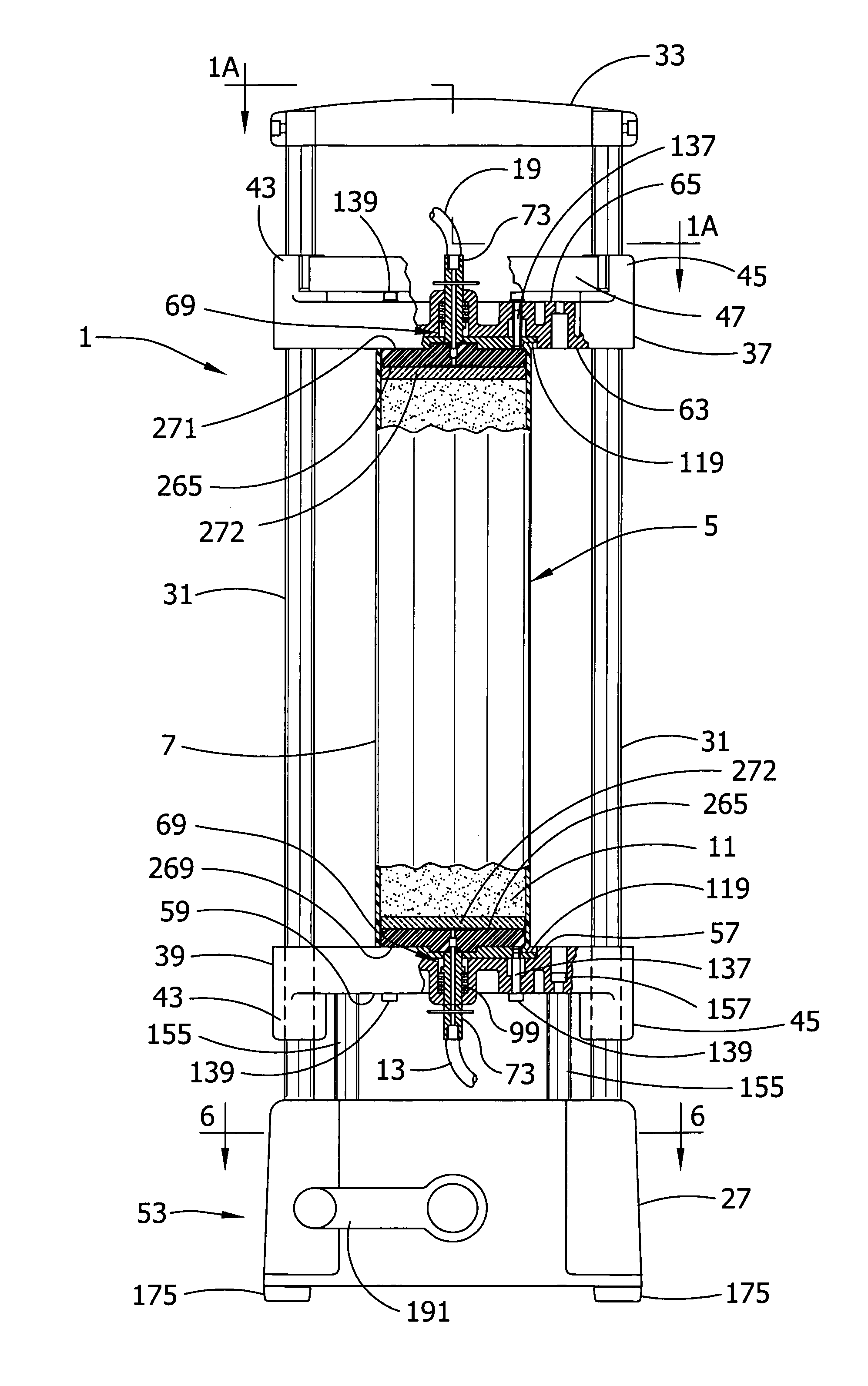
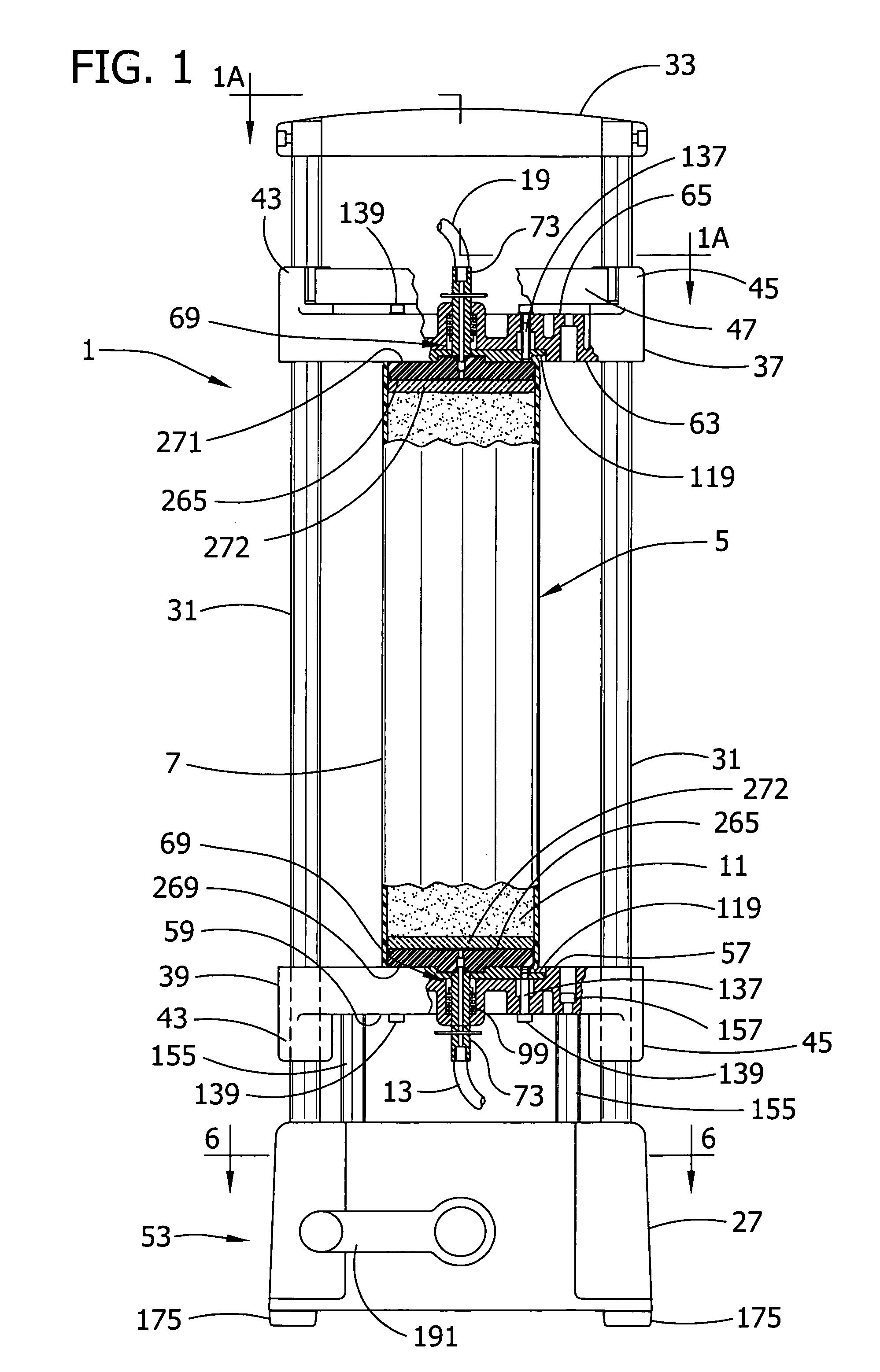
[0046] Referring now to the drawings, and more particularly to FIG. 1, one embodiment of a liquid chromatography stand of the present invention is designated in its entirety by the reference numeral 1. The stand can be used in a conventional High-Throughput Flash Purification (HTFP) system, generally designated 3 and shown in FIG. 14, to separate or purify a sample material. The stand 1 has a chromatography column, generally designated 5, which, in the embodiment of FIG. 1, comprises a single chromatography cartridge 7 containing a bed of chromatography media 11 that is in fluid connection with upstream tubing 13 connected to a pump 15 and downstream tubing 19 leading to a collection container 21. The pump 15 receives fluid from a supply container 23 and discharges solvent at a fluid pressure sufficient to convey the solvent through the cartridge 7. The collection container 21 receives the various sample components that flow through the bed of separating media 11 in the column 5 at ...


PUM

PropertyMeasurementUnit
obtuse angleaaaaaaaaaa

Abstract

A chromatography cartridge for use in a chromatography stand comprises a tube for containing chromatography media. An end cap is adapted to fit in an end of the tube for closing the end of the tube. The end cap has a generally cylindric body having an external axial surface at least partially received in the tube and an outer face. At least one protrusion extends from the external axial surface of the body. The protrusion is shaped and arranged to contact an interior surface of the tube to form a fluid-tight connection between the end cap and the tube.

Description

CROSS-REFERENCE TO RELATED APPLICATION [0001] This application is a Continuation-in-Part of U.S. patent application Ser. No. 10 / 621,813, filed Jul. 17, 2003, which is hereby incorporated herein by reference.BACKGROUND OF THE INVENTION [0002] The present invention relates generally to liquid chromatography apparatus, and more particularly to a liquid chromatography stand and chromatography cartridges and methods of use in a high throughput flash purification system. [0003] Liquid chromatography is well known in the art as a method for separating a complex mixture. Liquid chromatographic techniques employ separation of one or more components of a mixture from other components thereof by flow through a chromatographic column, followed by detection of the separated components with a flow-through detector. A mobile phase consisting of a carrier fluid (i.e., solvent) and a sample composition to be identified, analyzed, or purified is passed through the column containing a media (e.g., sil...

Claims


Application Information

Patent Timeline
Patent Type & Authority Applications(United States)
IPC IPC(8): B01D15/08B01D15/22G01N30/60
CPCB01D15/22G01N30/6026G01N30/6047G01N30/6091G01N30/6004
Inventor HELD, ROBERT O'NEILCOX, CARL DOUGLAS
Owner SIGMA ALDRICH CO LLC
Why Eureka
Try Eureka