Electromagnetic shield assembly with opposed hook flanges
a shield assembly and electromagnetic technology, applied in shielding materials, cables, electrical apparatus casings/cabinets/drawers, etc., can solve problems such as adverse effects, circuits affected, and sensitive and/or high frequency circuits
- Summary
- Abstract
- Description
- Claims
- Application Information
AI Technical Summary
Problems solved by technology
Method used
Image

Examples
Embodiment Construction
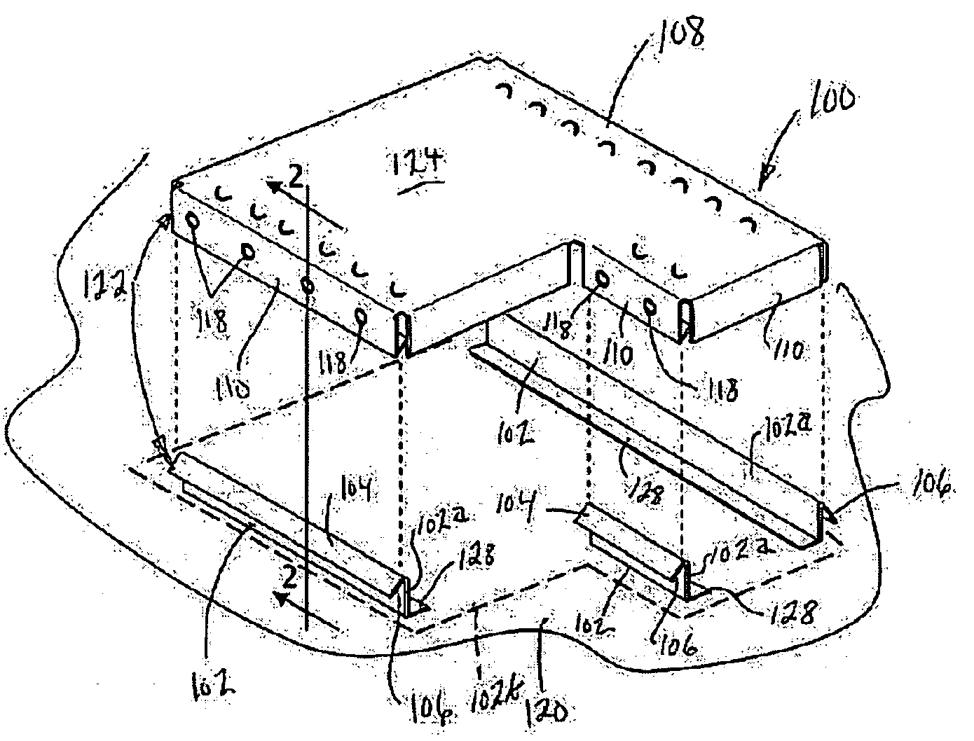
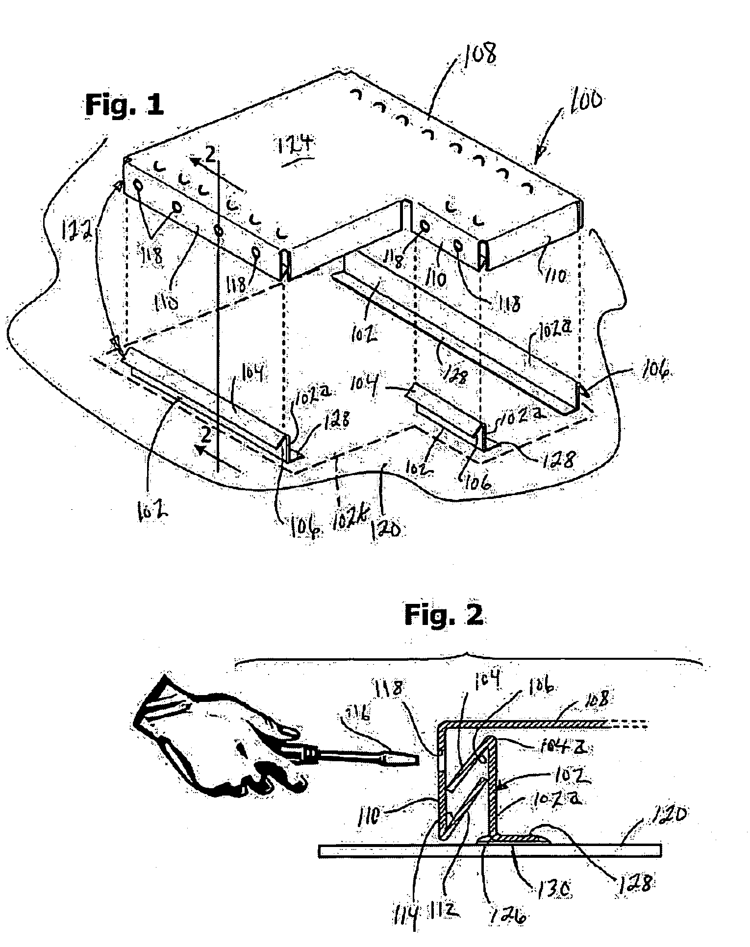
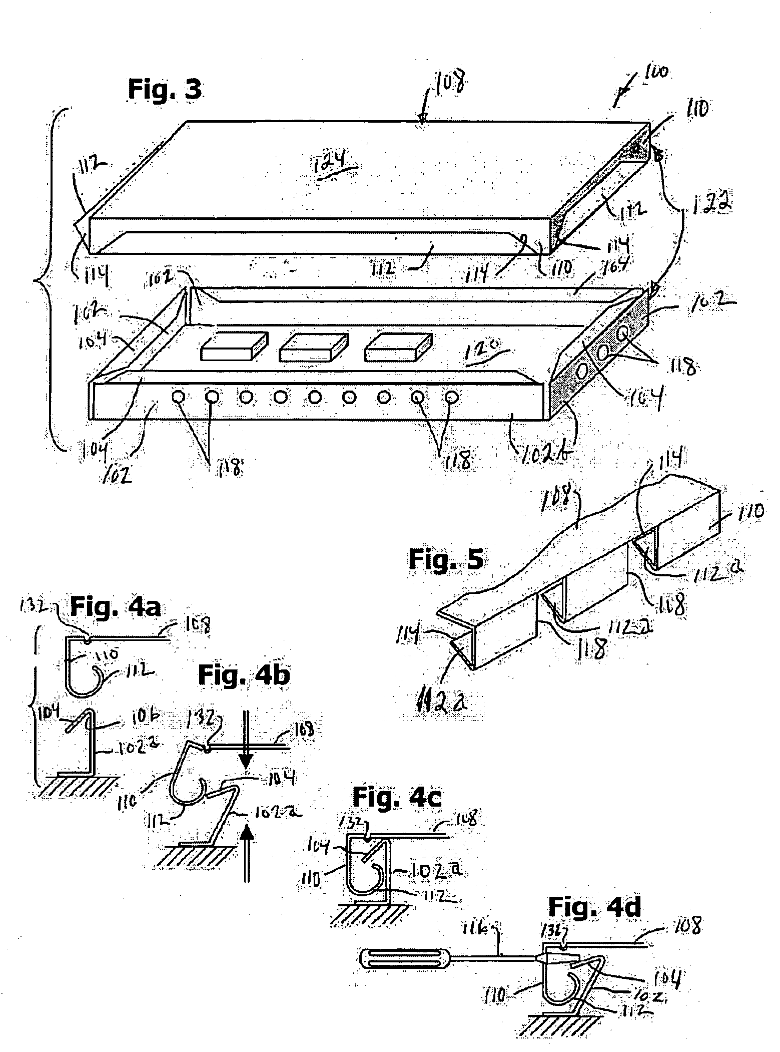
[0026] The inventive electromagnetic shielding structure, shown in FIGS. 1-5, involves an electromagnetic shield structure (100) having an elongated conductive support member (102) having a standing wall (102a) or fence (102a) that continuously or discontinuously defines a shielding perimeter (102b) and has a flange (104) laying over laterally to form a J-shaped hook (106) in cross section. A conductive cover (108) or lid engages over the standing wall (102) and has a depending side wall skirt (110) that has a flange (112) and forms a J-shaped hook (114) facing opposite from the hook (106) of the elongated wall (102). The cover (108) is pressed onto the wall (102) for assembly, causing the flanges (104) and (112) to deflect and snap over one another in the space between the overlapping skirt (110) and wall (102). The shield enclosure (100) can be disassembled without damage by applying a tool (116) through an opening (118) in the outer one of the skirt (110) and wall (102), to defle...
PUM
| Property | Measurement | Unit |
|---|---|---|
| electromagnetic shielding | aaaaa | aaaaa |
| conductive | aaaaa | aaaaa |
| perimeter | aaaaa | aaaaa |
Abstract
Description
Claims
Application Information
 - R&D Engineer
- R&D Manager
- IP Professional
- Industry Leading Data Capabilities
- Powerful AI technology
- Patent DNA Extraction
Browse by: Latest US Patents, China's latest patents, Technical Efficacy Thesaurus, Application Domain, Technology Topic.
© 2024 PatSnap. All rights reserved.Legal|Privacy policy|Modern Slavery Act Transparency Statement|Sitemap