Life preserver system

Active Publication Date: 2005-10-06
TULMAR SAFETY SYST
View PDF6 Cites 10 Cited by
  • Summary
  • Abstract
  • Description
  • Claims
  • Application Information

AI Technical Summary

Benefits of technology

[0015] In some embodiments, the inflatable life preserver further comprises one or more fasteners adapted to hold the life preserver in a stored configuration in which the head support folds to cover the self inflating means when the life preserver is in an uninflated state and wherein the expansion force of the g

Problems solved by technology

Such personnel often carry a significant amount of heavy equipment which

Method used


Image

  • Life preserver system
  • Life preserver system
  • Life preserver system

Examples


Embodiment Construction

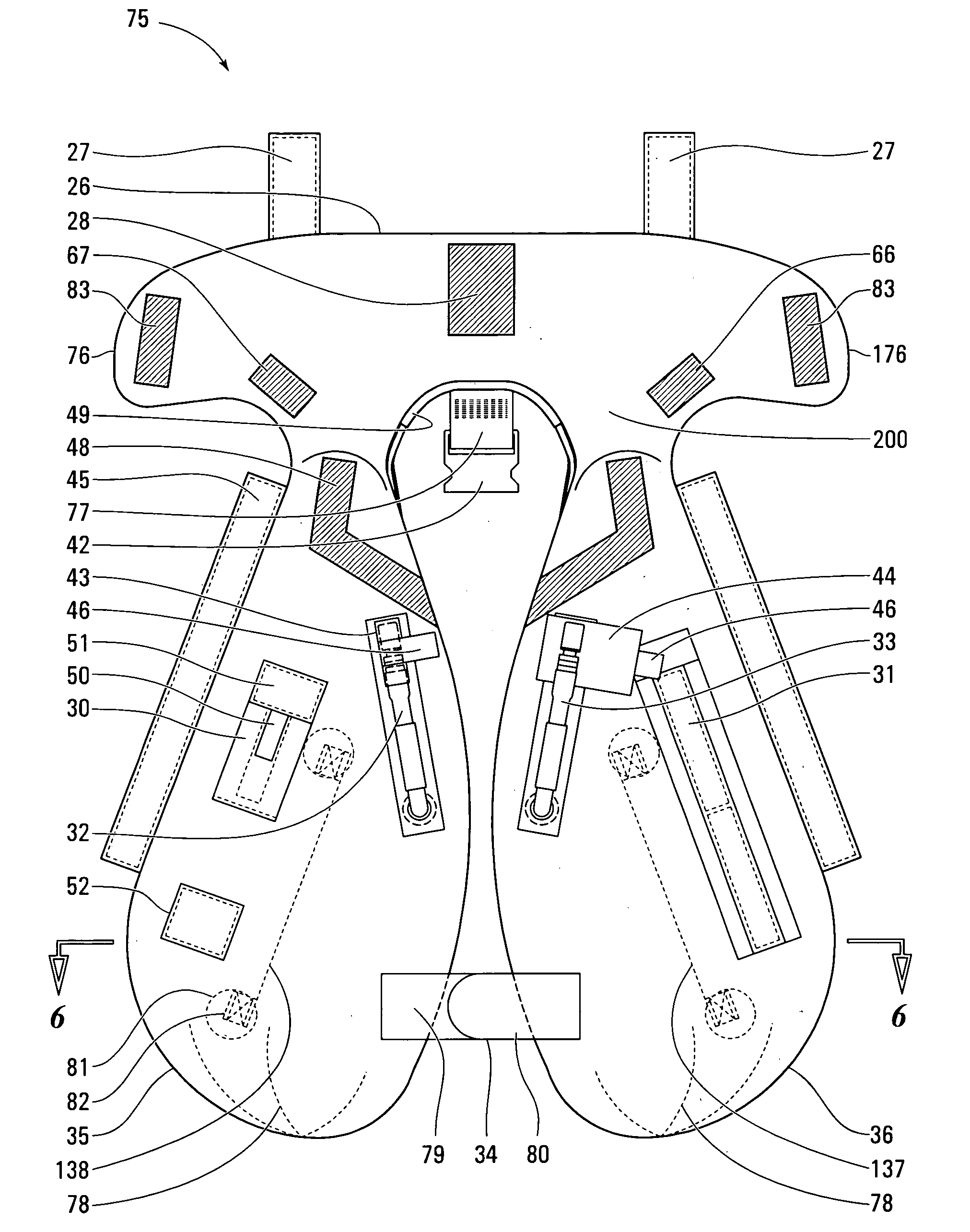
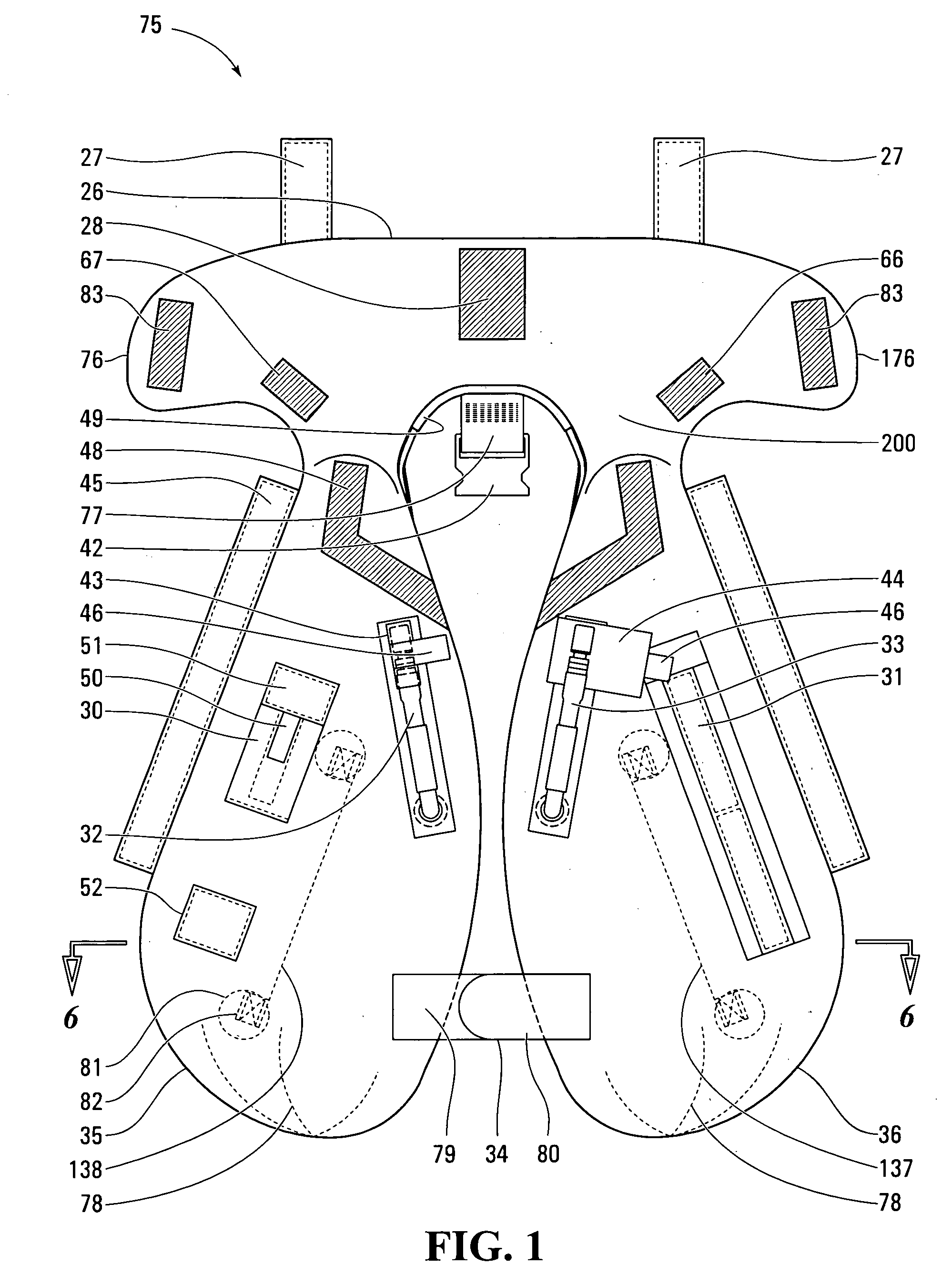
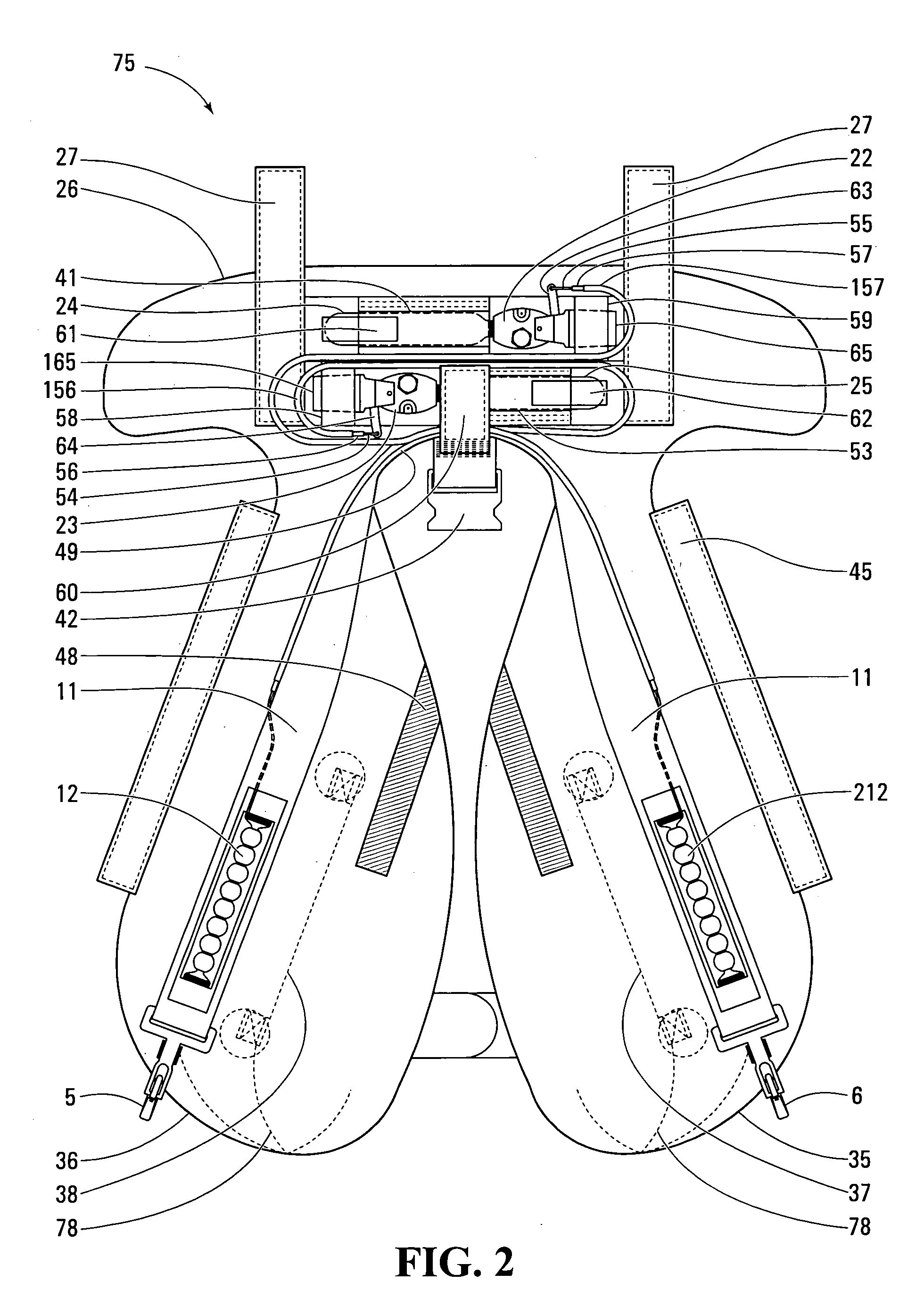
[0031]FIG. 1 shows a life preserver 75 in an inflated state. The life preserver 75 includes an overshell 200 which defines a left front pod 36, a right front pod 35, and a life preserver head support 26. The shape and size of the left front pod 36, the right front pod 35 and the life preserver head support 26 are defined by the overshell 200. The overshell 200 has no air retention requirements. The overshell 200 is comprised of a fabric which is sewn to define the shape of the life preserver 75. Accessories can be directly sewn to the overshell 200. Some stitching lines 78 are shown in FIG. 1 which indicate that the overshell 200 defines a three dimensional shape for the left front pod 36, the right front pod 35 and the life preserver head support 26 in the inflated state.

[0032] The life preserver head support 26 has a central portion, a left lobe 176 and a right lobe 76. The central portion of the life preserver head support defines an inward side which has an arc shaped to fit a ...


PUM


Abstract

An inflatable life preserver, capable of being in an inflated state and an uninflated state, is disclosed. The life preserver includes a structural overshell which defines the size and shape of the life preserver in the inflated state and a gas retention bladder fitted within the overshell. The overshell bears the expansion force of a gas within the bladder in the inflated state. The overshell defines inflatable side portions which are confined to sides of at least a portion of a chest area of a wearer, when the life preserver is in an uninflated state, and, which extend laterally over the chest area of the wearer, when the life preserver is in an inflated state.

Description

CROSS-REFERENCE TO RELATED APPLICATIONS [0001] The application claims priority from provisional patent application Ser. No. 60 / 558097 filed Apr. 1, 2004.FIELD OF THE INVENTION [0002] This invention relates to emergency floatation equipment, more particularly, to personal floatation devices or life preservers. BACKGROUND OF THE INVENTION [0003] Military, police and similar personnel have particular needs in respect of life preservers. Such personnel often carry a significant amount of heavy equipment which has little or no buoyancy. Accordingly, any life preserver worn by such personnel requires sufficient buoyancy to support the weight of the equipment as well as the wearer. Additionally, the life preserver should not affect their manoeuvrability or access to their equipment. Assault parties and casualty response units in particular require the protection of a life preserver which does not interfere with the operations the personnel need to perform. [0004] It is also desirable that ...

Claims


Application Information

Patent Timeline
IPC IPC(8): B63C9/08B63C9/125
CPCB63C9/1255
Inventor SMITH, JONATHANO'CONNELL, MICHAEL
Owner TULMAR SAFETY SYST
Why Eureka
Try Eureka