
Vehicle jack positioning device and method

a positioning device and vehicle jack technology, applied in the direction of lifting devices, safety devices for lifting equipment, vehicle maintenance, etc., can solve the problems of difficult to determine the proper position of the jack with any accuracy, the instructions provided in the owner's manual are often imprecise or ambiguous, and the jack point is difficult to locate and determine with any accuracy. , to achieve the effect of improving the efficiency of the vehicle jack and improving operator safety

Inactive Publication Date: 2005-11-24
RAYNOR NEIL M
View PDF19 Cites 10 Cited by
  • Summary
  • Abstract
  • Description
  • Claims
  • Application Information

AI Technical Summary

Benefits of technology

[0007] The methods and devices of the invention are useful to assist the jack operator in determining the proper position of the jack and improve vehicle jack efficiency and operator safety. Advantageously, this invention may be used with any type of vehicle jack well-known by those having ordinary skill in the art including, but not limited to, scissor jacks, tripod jacks, and hydraulic jacks.

Problems solved by technology

However, on many vehicles, the jack point is difficult to locate and determine with any accuracy.
Because the jack point is generally located on the underside of the vehicle frame near the vehicle wheels, the proper position for the jack is often difficult to determine by feel or visual inspection.
Additionally, the instructions provided in an owner's manual are often imprecise or ambiguous.
Often jack operators are guided by only their visual inspection of the vehicle frame resulting in an imprecise estimate as to the proper jack point.
Further, determination of the proper jack point is particularly difficult when jack operation is conducted in the dark; during inclement weather; on a vehicle frame residing low to the level surface; and / or by an operator having physical or ocular limitations or impairments.
Additionally, structural indicators provided on the vehicle frame at the proper jack point can wear away, fade and lose definition, often due to rusting on the underside of the vehicle frame.
Operation of a jack in an improper position relative to the vehicle can damage the vehicle or cause the vehicle to slip off the jack and expose the operator to physical injury.

Method used


Image

  • Vehicle jack positioning device and method
  • Vehicle jack positioning device and method
  • Vehicle jack positioning device and method

Examples


Embodiment Construction

[0011] The jack positioning devices of the invention employ a sensor to detect an indicator located at the proper point on the vehicle frame for placement of the vehicle jack and to indicate by light, sound, or both when the jack is aligned with the jack point. As used herein, the term “jack point” means the proper location on the vehicle where a vehicle jack is to make contact with the vehicle during operation of the jack and raising of the vehicle. Preferably, the term jack point means the optimal location on the vehicle frame where the jack acts on the vehicle during operation of the jack and raising of the vehicle. More preferably, the term jack point means a position near the vehicle's tires where a jack makes contact and applies force to raise the vehicle during operation of the jack.

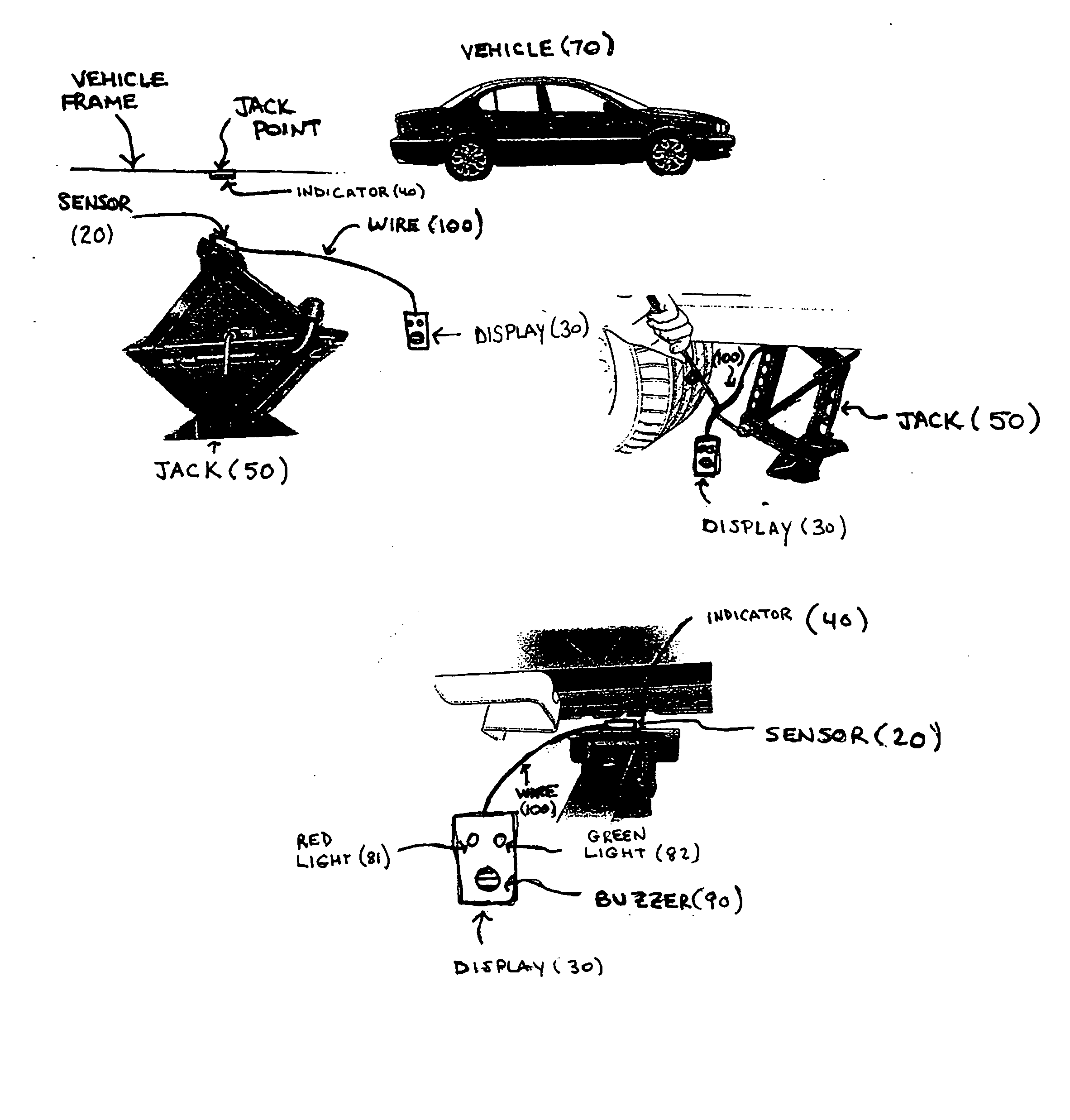
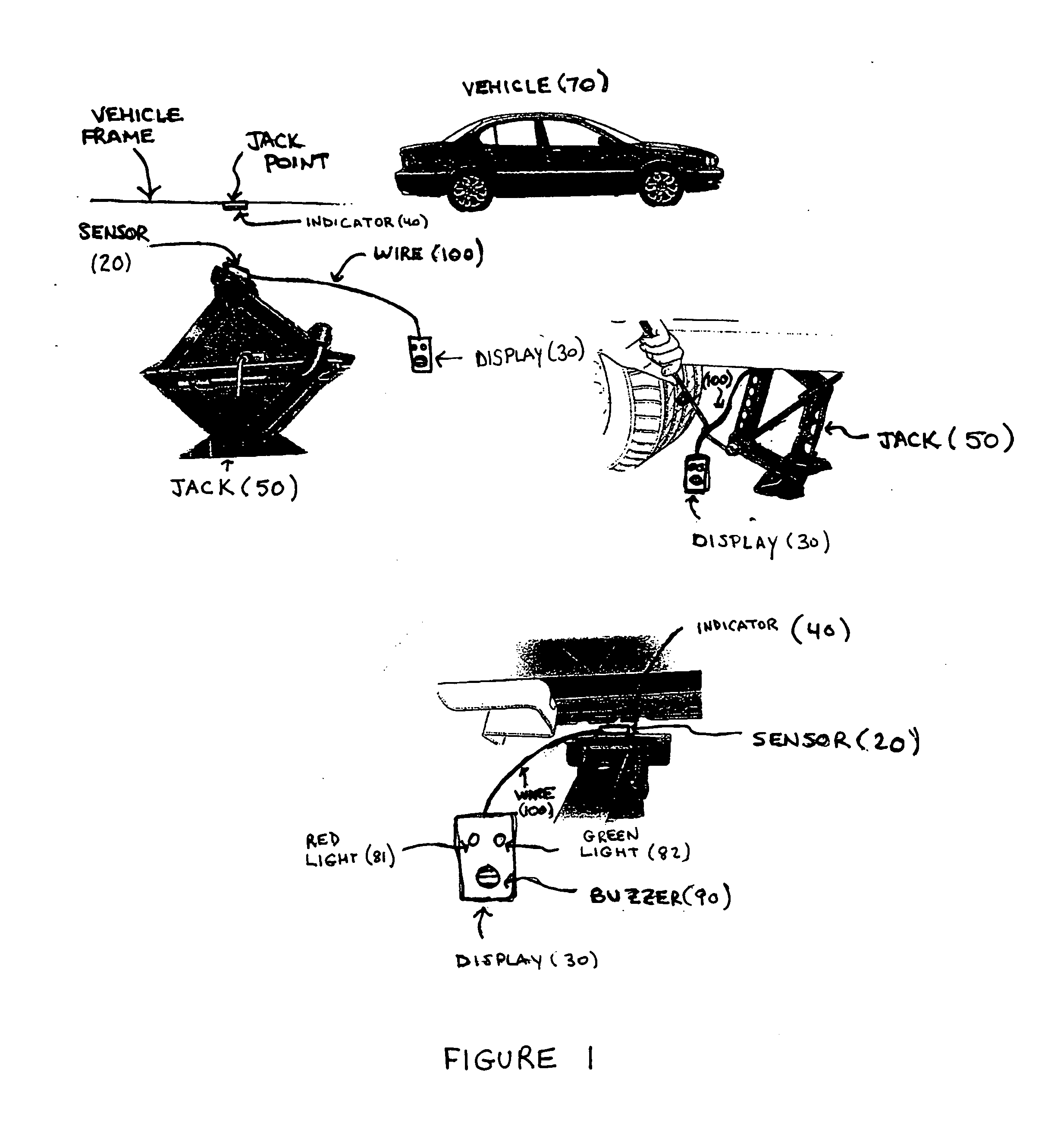
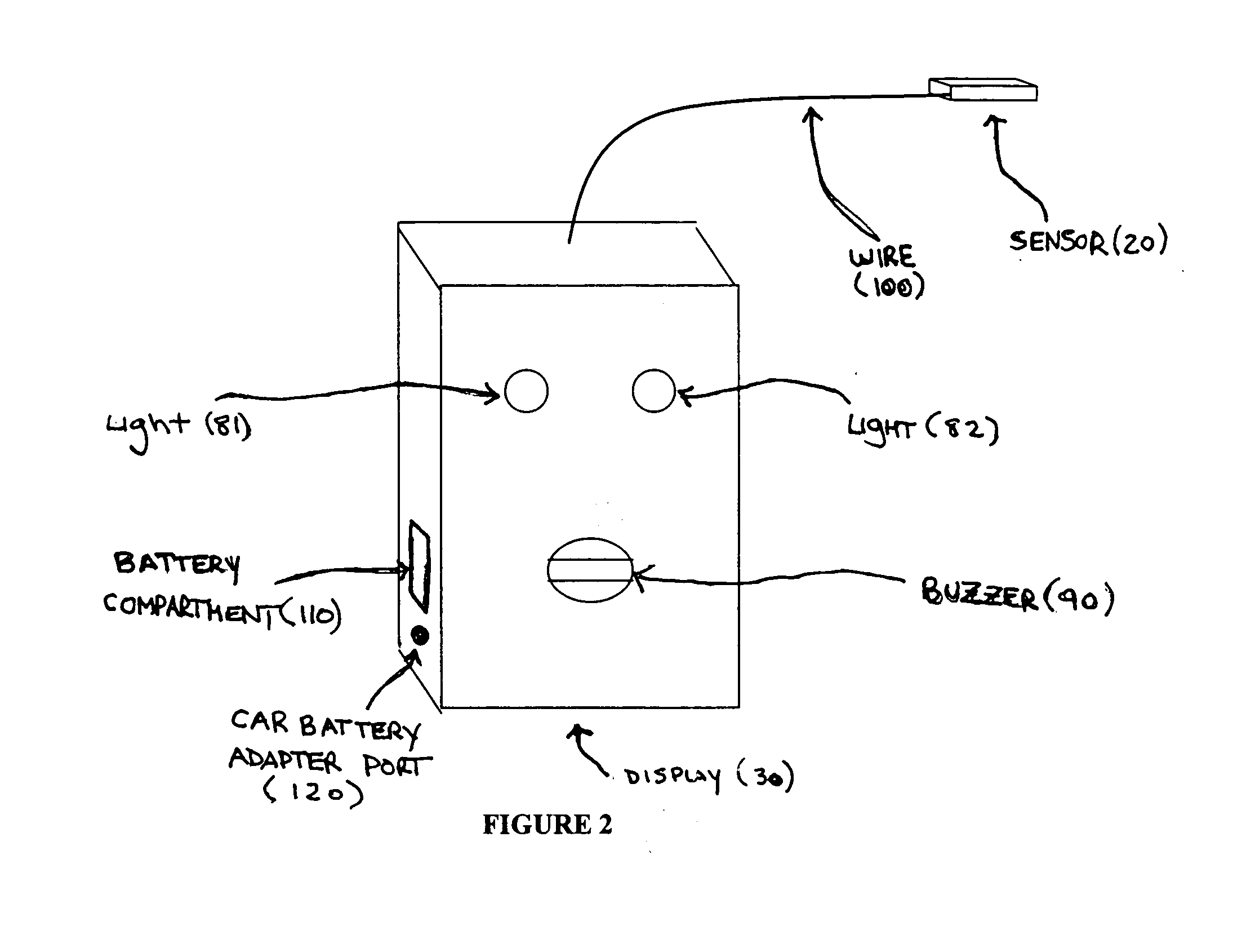
[0012]FIGS. 1 and 2 depict jack positioning device 10 according to the invention. Jack positioning device 10 comprises sensor 20 in communication with display 30. Sensor 20 is adapted to attach t...


PUM


Abstract

A novel device and method for positioning a vehicle jack in relation to a vehicle. The device uses a sensor which communicates with an indicator located at the point on the vehicle frame for proper placement of the vehicle jack, or jack point. The sensor detects the indicator's position when brought into substantial alignment and proximal range with the indicator to determine the proper position of the vehicle jack in alignment with the jack point. Upon detection of the indicator by the sensor, the display of the device provides a visual or auditory signal to the jack operator indicating location of the jack point.

Description

FIELD OF THE INVENTION [0001] This invention relates to novel devices and methods for positioning a vehicle jack relative to a vehicle. Particularly, the invention relates to devices for determining the proper location on the vehicle frame for placement of the vehicle jack during operation of the jack. BACKGROUND OF THE INVENTION [0002] Vehicle jacks are frequently used to elevate a vehicle to facilitate vehicle maintenance and repair activities, such as changing a tire or inspecting the brakes. Virtually all vehicles require the vehicle jack to be positioned relative to and make contact with the vehicle in an optimal spot, or jack point, to effectuate efficient and safe operation of the jack. The jack point is determined by the vehicle manufacturer based on the features of the vehicle and associated lift equipment, such as vehicle weight, tire size and jack size. The jack point is often described in the vehicle owner's manual and / or indicated on the vehicle by a recess or depressed...

Claims


Application Information

Patent Timeline
Patent Type & Authority Applications(United States)
IPC IPC(8): B60S11/00B66F3/00B66F3/12B66F17/00
CPCB60S11/00B66F17/00B66F3/12
Inventor RAYNOR, NEIL M.
Owner RAYNOR NEIL M
Learn More