
Image processing method, apparatus and program
a technology of image processing and apparatus, applied in the field of image processing methods and apparatus, can solve the problems of long processing time, inability to obtain satisfactory results, and inability to achieve satisfactory results, and achieve the effect of excellent tonal reproduction
- Summary
- Abstract
- Description
- Claims
- Application Information
AI Technical Summary
Benefits of technology
Problems solved by technology
Method used
Image

Examples
first embodiment
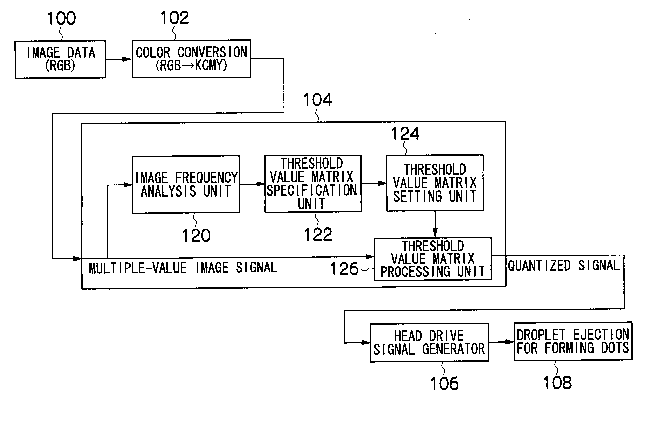
[0151]FIGS. 9A to 9C show threshold value matrices which are used in the aforementioned binarization processing. The high-frequency threshold value matrix 200 shown in FIG. 9A is a threshold value matrix having a size of m×m, which is used when the spatial frequency of the block under examination is a high frequency. Moreover, the medium-frequency threshold value matrix 202 shown in FIG. 9B is a threshold value matrix having a size of (2×m)×(2×m), which is used when the spatial frequency of the block under examination is a medium frequency. Furthermore, the low-frequency threshold value matrix 204 shown in FIG. 9C is a threshold value matrix having a size of (4×m)×(4×m), which is used when the spatial frequency of the block under examination is a low frequency.
[0152] The medium-frequency threshold value matrix 202 and the low-frequency threshold value matrix 204 shown in FIGS. 9B and 9C can be divided into sub-matrices by taking the size of the high-frequency threshold value matrix...
second embodiment
[0183] Next, a second embodiment of the present invention will be described.
[0184] In the present embodiment, in addition to a threshold value matrix as illustrated in the first embodiment described above, suitable threshold value matrices are used in accordance with changes in spatial frequency characteristics in the respective oblique directions, leftwards, rightwards, upwards and downwards. FIGS. 14A to 14C show threshold value matrices according to the second embodiment.
[0185]FIG. 14A shows a H / L threshold value matrix 240 used for an image block in which the spatial frequency changes from low-frequency to high-frequency; FIG. 14B shows a M / L threshold value matrix 242 used for an image block in which the spatial frequency changes from low-frequency to medium-frequency; and FIG. 14C shows a M / H threshold value matrix 244 used for an image block in which the spatial frequency changes from medium-frequency to high-frequency.
[0186] The H / L threshold value matrix 240, the M / L thr...
PUM
 Abstract
Description
Claims
Application Information