Optical accessory with mounting rail

a technology of optical accessories and mounting rails, applied in the field of optical accessories, can solve problems such as unmanageability

Inactive Publication Date: 2005-12-08
PIKIELNY DOV
View PDF6 Cites 109 Cited by
  • Summary
  • Abstract
  • Description
  • Claims
  • Application Information

AI Technical Summary

Problems solved by technology

A handheld light, such as a flashlight, can provide illumination, but it becomes unmanageable when the gun user must use both hands to control the gun.

Method used


Image

  • Optical accessory with mounting rail
  • Optical accessory with mounting rail
  • Optical accessory with mounting rail

Examples


Embodiment Construction

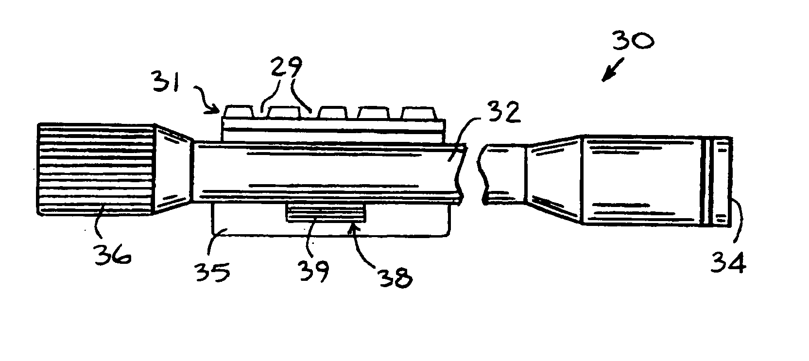
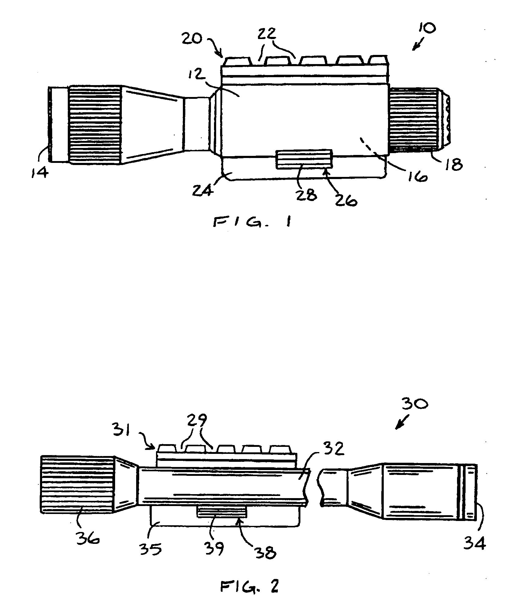
[0011] Reference is now made to FIG. 1, which illustrates an optical accessory 10, constructed and operative in accordance with an embodiment of the present invention.

[0012] Optical accessory 10 may comprise a flashlight (e.g., weapon light) having a casing 12, which includes a light 14 and a battery 16 disposed therein. A switch 18 may be used to operate the light 14, such as but not limited to, a momentary toggle / push switch or a constant-on shuttle switch. Light 14 may comprise any suitable light, such as but not limited to, a directional light, an infrared light, an ultraviolet light, and / or a blinking light, with any power and output of lumens.

[0013] Optical accessory 10 may be manufactured as one integral unit, with casing 12 supplied with light 14, battery 16 and switch 18. Alternatively, any commercial light may be mounted in casing 12. For example, light 14 may include the X200 weapon light, commercially available from SureFire, which includes a total internal refection f...


PUM


Abstract

An optical accessory including a first attachment device for mounting another optical accessory thereto, the first attachment device including a mounting rail, which may be formed with grooves. The optical accessory may further include a second attachment device adapted to be attached to a mounting rail external to the optical accessory.

Description

FIELD OF THE INVENTION [0001] The present invention relates generally to optical accessories, e.g., for weapons, such as but not limited to, flashlights and telescopic sights, and particularly to such accessories with mounting rail features. BACKGROUND OF THE INVENTION [0002] Police officers and other individuals who use guns in dark conditions often desire a portable light to illuminate their surroundings. A handheld light, such as a flashlight, can provide illumination, but it becomes unmanageable when the gun user must use both hands to control the gun. Accordingly, many weapon manufacturers today manufacture and market weapons with provisions for mounting a light on the weapon. For example, the major handgun manufacturers, such as Springfield Armory, Glock, SIG and many others, make handguns with a light mounting rail formed on the pistol / rifle frame, such as on the underside or top or both sides of the barrel. Such a mounting rail is often referred to in the art as a “light rai...

Claims


Application Information

Patent Timeline
Patent Type & Authority Applications(United States)
IPC IPC(8): F41G1/35F41G1/387
CPCF41G11/003F41G1/35
Inventor PIKIELNY, DOV
Owner PIKIELNY DOV
Why Eureka
Try Eureka