Vascular guidewire system

a guidewire and vascular technology, applied in the field of medical devices, can solve the problems of affecting the caliber, flexibility, direction, and the development of disease within the vessel, and achieve the effects of low profile, convenient positioning, and saving time and other resources

Inactive Publication Date: 2005-12-08
WINDCREST
View PDF42 Cites 49 Cited by
  • Summary
  • Abstract
  • Description
  • Claims
  • Application Information

AI Technical Summary

Benefits of technology

[0014] The guidewire apparatus, methods and systems according to the present invention, in their various aspects, address any of a range of problems associated with the manipulation of catheters and guidewires within vascular systems during invasive diagnostic or interventional radiologic procedures or in other fields requiring precisely controlled penetration of narrow passageways. Among other advantages, embodiments of the present invention provide variable control, steerable guidewires and associated controllers that may have one more of the following advantages: coaxial structure, over-the-wire catheter compatibility, remote controllability, variably deflectable tip, guidewire low profile, controllability by a detachable, side-entry, easily positioned, single-handedly manipulated, combination torque and guidewire tip control device, ergonomic controllability from a

Problems solved by technology

Even when healthy, the anatomy of these vessels is complex, with numerous divisions leading into progressively smaller branches.
Development of disease within these vessels often complicates matters by altering their caliber, flexibility, and direction.
These obstructions may complicate the vascular anatomy by leading to the formation of new collateral pathways that establish new routes around the obstructions in order to provide blood flow down-stream from the blockage.
The negotiation of the complex vascular anatomy, even when healthy, can be difficult, time consuming and frustrating.
When narrowed or obstructed by disease, the vessels are even more difficult—and sometimes impossible—to negotiate.
A distinct disadvantage of these pre-formed devices is a need to co

Method used


Image

  • Vascular guidewire system
  • Vascular guidewire system
  • Vascular guidewire system

Examples


Embodiment Construction

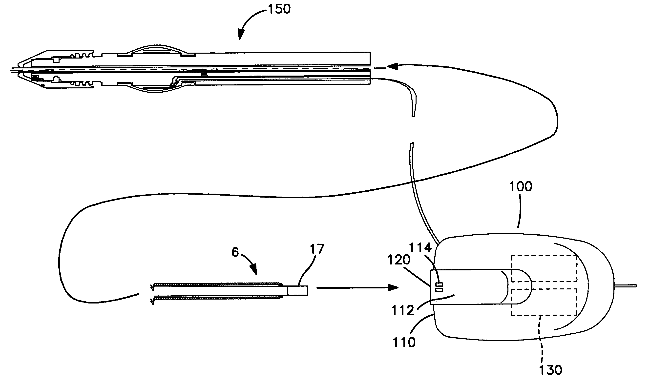
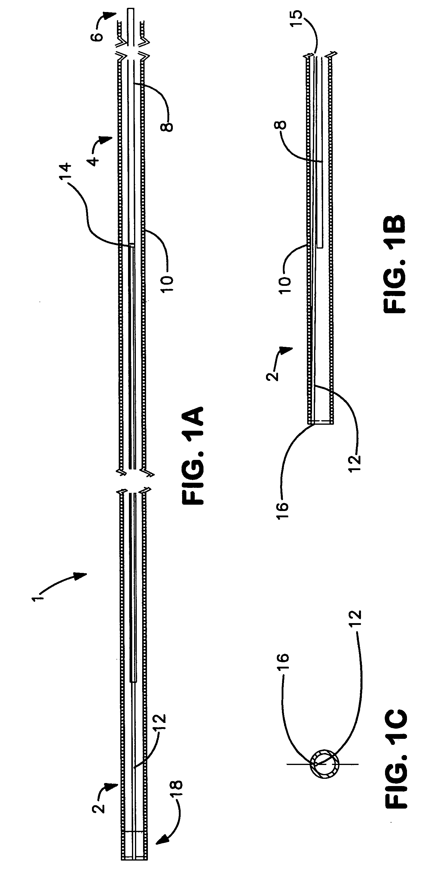
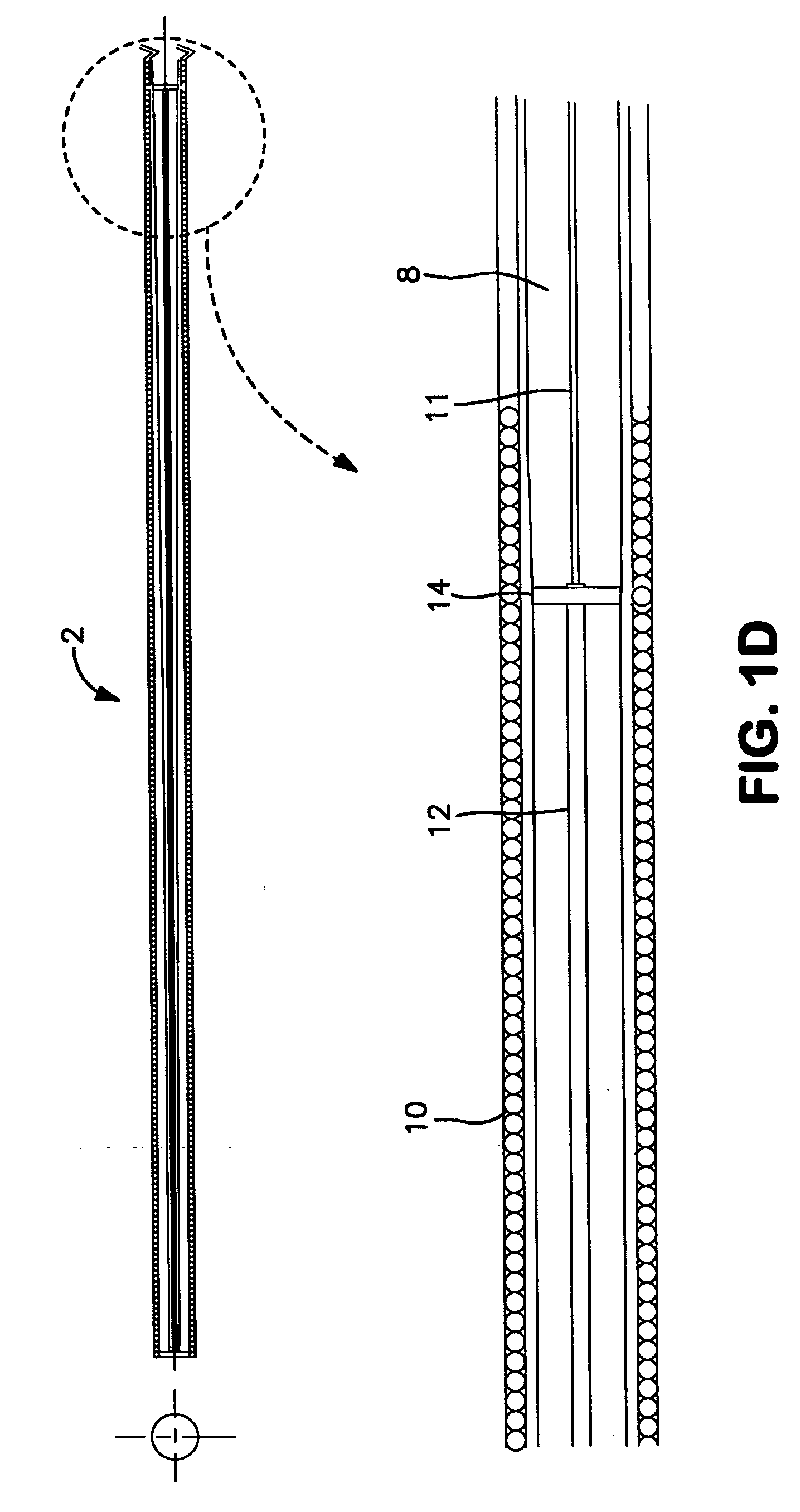
[0043]FIGS. 1A-1F show various views of an embodiment of a guidewire 1 according to the present invention. Guidewire 1, shown fragmented in FIG. 1A to permit the entirety of the guidewire to be shown in one figure, comprises three main sections. Guidewire 1 includes an elongate, tubular structure, having a proximal end 6 (see FIG. 1F) which resides exterior to the body of a patient (or other passageway with which guidewire 1 is being used) and physically handled by a practitioner, and distal end, which in use will be within the passageway, having an actuator portion 2. The actuator portion 2 at a most distal portion of the guidewire 1 comprises a shape memory alloy (SMA) 12 or other suitable component adapted to introduce a deflection in a tip of guidewire 1, when activated. A third, central or mid-portion 4 of guidewire 1 is that section of the guidewire 1 between, and coupling, the distal and proximal portions and contains an inner, centrally disposed, electrically insulated, cond...


PUM


Abstract

A vascular guidewire in an embodiment of the present invention, having such features as uniform diameter, low-profile cross section over its length and a distal tip capable of deflection and variable configurations, provides a range of advantages. A variable distal tip of shape-memory alloy deflects into varied configurations when remotely actuated. Such actuation, according to an aspect of the present invention, can be by way of a side entry, easily repositioned, single-handed controller that allows both rotational control of the guidewire and control of the variable tip. In another aspect, a longitudinal element in the guidewire, such as an exterior wire wrap, can provide dual functionality, including structural support as well as an electrical path for use in energizing, and thus deflecting, the distal tip. In yet another aspect, the overall guidewire geometry having constant circumference and low profile, as well as side-access controllability, permits advantageous coaxial mounting and removal of catheters over the proximal guidewire end and facilitates insertion and removal of guidewires through catheters in vivo.

Description

CROSS-REFERENCE TO RELATED APPLICATIONS [0001] This patent application claims priority benefit under 35 U.S.C. § 119(e) of U.S. Provisional Patent Applications 60 / 555,858, filed Mar. 24, 2004, and 60 / 632,580, filed Dec. 1, 2004, the contents of which applications are incorporated herein by reference in their entirety.FIELD OF THE INVENTION [0002] The present invention relates in general to the field of medical devices and, in particular, to devices for use in interventional and diagnostic access, manipulation within, and negotiation of, the vascular system. BACKGROUND OF THE INVENTION [0003] The vascular field of medicine relates to the diagnosis, management and treatment of diseases affecting the arteries and veins. Even when healthy, the anatomy of these vessels is complex, with numerous divisions leading into progressively smaller branches. Development of disease within these vessels often complicates matters by altering their caliber, flexibility, and direction. The interior, or...

Claims


Application Information

Patent Timeline
IPC IPC(8): A61B5/00A61M25/00A61M25/01A61M25/09A61N1/00
CPCA61M25/0105A61M25/0136A61M25/0158A61M25/09A61M25/09016A61M25/09041A61M2025/09083A61M2025/09141A61M2025/09175
Inventor WHITTAKER, DAVID R.LAURITZEN, KEITH E.WHITTAKER, ALLISON M.
Owner WINDCREST
Why Eureka
Try Eureka