Electrochemical element

Inactive Publication Date: 2005-12-15
PANASONIC CORP
View PDF4 Cites 23 Cited by
  • Summary
  • Abstract
  • Description
  • Claims
  • Application Information

AI Technical Summary

Benefits of technology

[0013] The present invention has been made in view of the above problems in the conventional techniques. It is an object of the present invention t

Problems solved by technology

In this case, when only one portion of the current collector is connected to the portion serving as an external connection terminal, a current path from a distant portion in the wound strip-shaped current collector to the connected portion becomes longer, resulting in an increase in electrical loss and temperature rise during a high-rate charge/discharge.
However, in the configuration disclosed in Japanese Patent Laid-Open Publication No. 2000-294222 in which a flat surface is formed through bending a current collector protruded from an end and welded with a current collector plate placed thereon, the welding conditions cannot be stabilized when a thin electrode current collector is employed

Method used


Image

  • Electrochemical element
  • Electrochemical element
  • Electrochemical element

Examples


Embodiment Construction

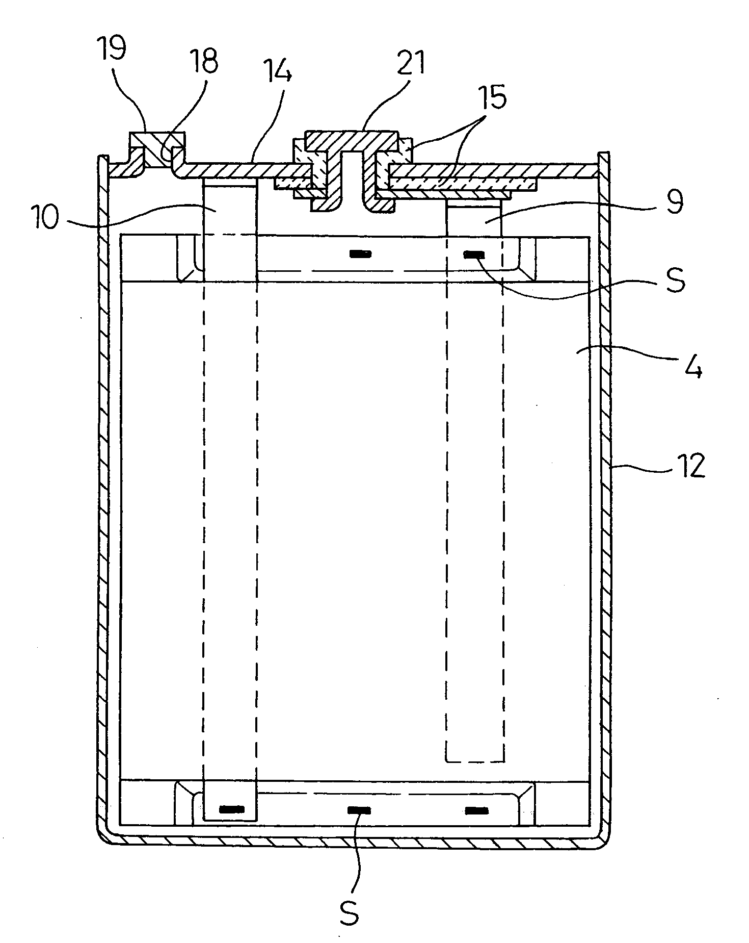
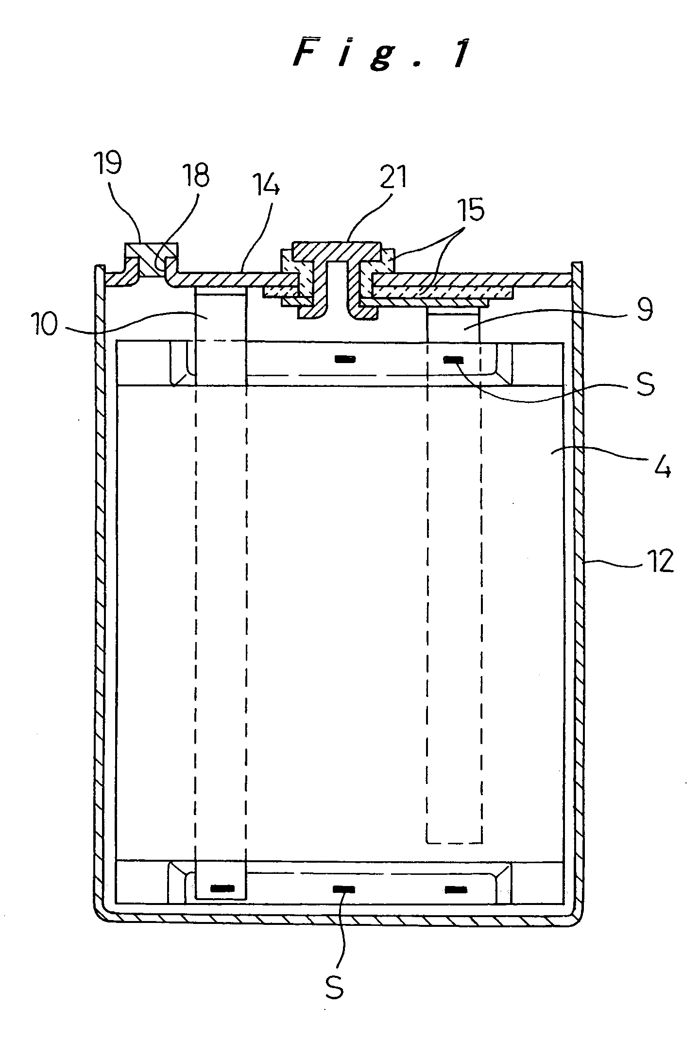
[0027] In the present embodiment, the connection structure according to the present invention is applied to a lithium ion rechargeable battery which is an example of an electrochemical element. As shown in FIG. 1, the lithium ion rechargeable battery according to the present embodiment has an outer shape of a flat prismatic shape, and comprises an electrode assembly 4 accommodated in a battery case 12. The electrode assembly 4 is formed by winding a positive electrode and a negative electrode with a separator interposed therebetween such that the cross section thereof has an ellipsoidal shape. A positive lead 9 pulled out from the positive electrode is electrically connected to an external positive connection terminal 21 provided in a sealing plate 14 which seals the opening of the battery case 12 and is insulated from the external positive connection terminal 21. A negative lead 10 is pulled out from the negative electrode and is connected to the sealing plate 14.

[0028] As shown i...


PUM


Abstract

The electrochemical element includes an electrode assembly accommodated in a case with an electrolyte. The electrode assembly is formed into a flat shape by winding positive and negative electrodes with a separator interposed therebetween. The positive electrode includes an exposed positive current collector portion uncoated with an active material and formed in one end in the width direction of a strip-shaped positive current collector, and a positive lead is attached to the exposed positive current collector portion. The negative electrode includes an exposed negative current collector portion uncoated with an active material and formed in the other end in the width direction of a strip-shaped negative current collector, and a negative lead is attached to the exposed current collector portion. The exposed positive current collector portion on the one end is pressed and welded, and the exposed negative current collector portion on the other end is pressed and welded to form the electrode assembly. This implements a current collection structure for providing stable conductive connection with high quality in a simple manner for an electrochemical element requiring high power.

Description

[0001] The present disclosure relates to subject matter contained in priority Japanese Patent Application No. 2004-175186 filled on Jun. 14, 2004, the contents of which is herein expressly incorporated by reference in its entirety. BACKGROUND OF THE INVENTION [0002] 1. Field of the Invention [0003] The present invention relates to an electrochemical element such as a battery or an electric double layer capacitor having a prismatic outer shape and comprising an electrode assembly composed of positive and negative electrodes wound into a flat shape, and being accommodated into a case together with an electrolyte. In particular the invention relates to an electrochemical element having a current collection structure designed for high power output. [0004] 2. Description of the Related Art [0005] In an electrochemical element such as a battery or an electric double layer capacitor, an electrode assembly having a winding structure composed of positive and negative electrodes wound with a ...

Claims


Application Information

Patent Timeline
IPC IPC(8): H01G11/00H01G11/52H01M50/528H01G11/66H01G11/70H01G11/74H01G11/86H01M4/13H01M10/04H01M10/05H01M10/0525H01M10/0566H01M10/0587H01M50/536H01M50/538
CPCH01M2/263H01M4/13H01M10/0431Y02T10/7011H01M10/0587Y02E60/122H01M10/0525Y02E60/10H01M50/538Y02P70/50H01M50/536
Inventor KOZUKI, KIYOMI
Owner PANASONIC CORP
Why Eureka
Try Eureka