

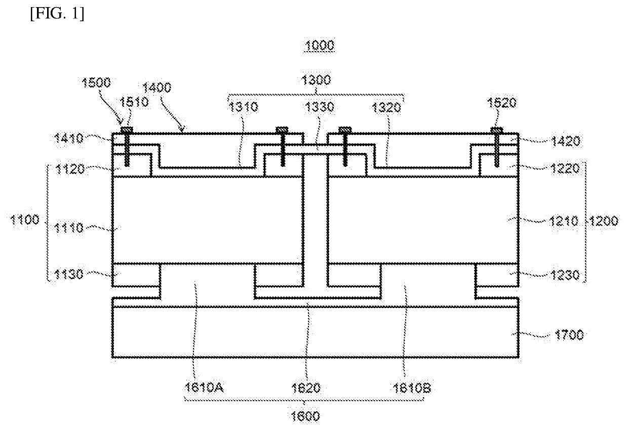
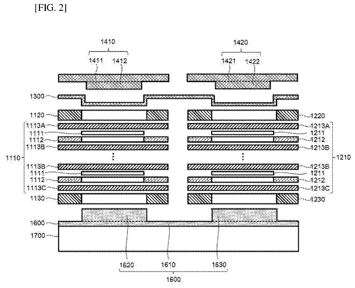
Fuel cell stack structure
a technology of stack array and fuel cell, which is applied in the direction of fuel cells, fuel cell details, collectors/separators, etc., can solve the problems of electric energy loss, and achieve the effect of improving current collection efficiency and improving current collection efficiency
- Summary
- Abstract
- Description
- Claims
- Application Information
AI Technical Summary
Benefits of technology
Problems solved by technology
Method used
Image

Examples
Embodiment Construction
[0025]Hereinafter, an embodiment of the present disclosure will now be described in detail with reference to the accompanying drawings. The present disclosure is intended to illustrate certain embodiments of the present disclosure and to explain the present disclosure in detail in the text, as it may make various changes and may take various forms. It should be understood, however, that the present disclosure is not intended to be limited to any particular form of disclosure, but includes all modifications, equivalents, and alternatives falling within the spirit and scope of the present disclosure. Throughout the disclosure, like reference numerals refer to like parts throughout the various FIGS. and embodiments of the present disclosure. In the accompanying drawings, the dimensions of the structures are shown enlarged or reduced in order to clarify the present disclosure.
[0026]Furthermore, terms used in this application are simply used to describe particular embodiments and are not...
PUM
| Property | Measurement | Unit |
|---|---|---|
| conductive | aaaaa | aaaaa |
| electrical energy | aaaaa | aaaaa |
| chemical energy | aaaaa | aaaaa |
Abstract
Description
Claims
Application Information