Rechargeable battery

a rechargeable battery technology, applied in the manufacture of cell components, final product details, cell components, etc., can solve the problems of deviating from the current collecting plate, affecting and the uncoated region of the anode or the cathode cannot be fully welded to the uncoated region at the edge region, so as to achieve improved current collecting efficiency and high resistance to impa

Active Publication Date: 2015-05-26
SAMSUNG SDI CO LTD
View PDF38 Cites 0 Cited by
  • Summary
  • Abstract
  • Description
  • Claims
  • Application Information

AI Technical Summary

Benefits of technology

[0017]Aspects of the present invention provide a rechargeable battery having advantages of having improved current collecting efficiency and high resistance to impact and shock.
[0029]According to an embodiment of the present invention, since a contact area between the current collecting plate and the uncoated region is increased by the guide portion of the current collecting plate, current collecting efficiency can be improved.
[0030]Also, according to an embodiment of the present invention, the center of the current collecting plate can aligned with the center of the electrode assembly by the guide portion when the current collecting plate is secured to the electrode assembly. Thus, the current collecting plate can be easily disposed on and secured to the electrode assembly.
[0031]In addition, according to an exemplary embodiment of the present invention, the insulation member disposed on the current collecting plate is secured in a state wherein the beading portion of the case presses the insulation member. Accordingly, the current collecting plate is prevented from moving in response to a shock or a vibration applied from the outside.
[0032]Further, according an embodiment of the present invention since the insulation member has a ring shape, the insulation member does not have any specific directional orientation so the insulation member can be easily disposed on and secured to the current collecting plate.

Problems solved by technology

However, conventional current collecting plates cannot be fully welded to the uncoated region at edge regions of the current collecting plates, particularly by laser welding because, when a laser is irradiated at the edge regions of the current collecting plates, the laser may deviate from the current collecting plates and may damage the uncoated region of the anode or cathode.
If the uncoated region located at an edge region of an anode or cathode cannot be connected to the current collecting plate, the output of the rechargeable battery may deteriorate since charges collected at the edge regions cannot move to a current collecting plate.
However, consistent alignment is very difficult because the cross-sections of the current collecting plates are smaller than the cross-section of the electrode assembly.

Method used


Image

  • Rechargeable battery
  • Rechargeable battery
  • Rechargeable battery

Examples


Embodiment Construction

[0049]Reference will now be made in detail to the present embodiments of the present invention, examples of which are illustrated in the accompanying drawings, wherein like reference numerals refer to the like elements throughout. The embodiments are described below in order to explain the present invention by referring to the figures.

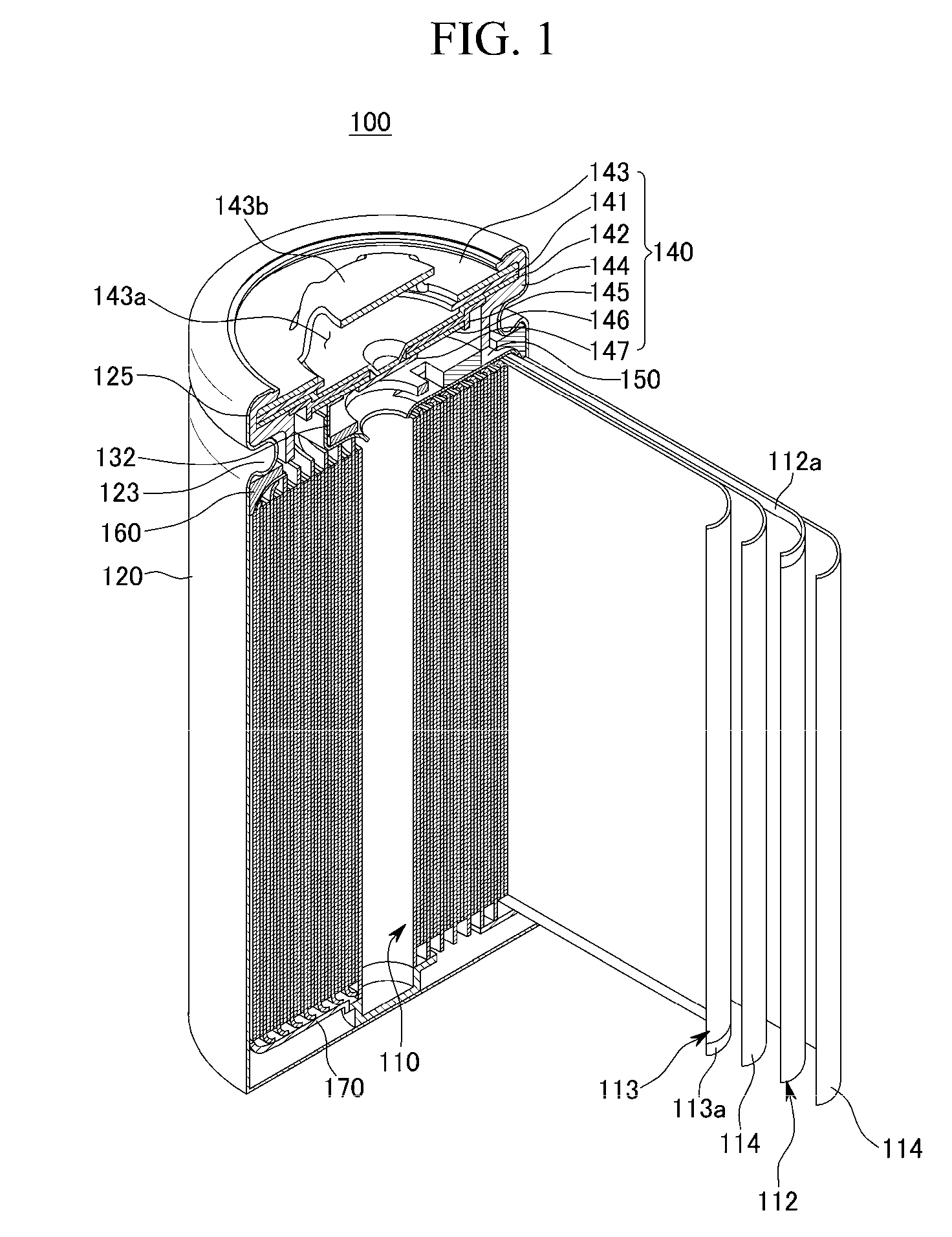
[0050]FIG. 1 is a cross-sectional perspective view of a rechargeable according to a first exemplary embodiment of the present invention, including a partially exploded view of the electrode assembly of the rechargeable battery. Referring to the FIG. 1, the rechargeable battery 100 according to the present exemplary embodiment includes an electrode assembly 110 and a case 120. The electrode assembly 110 has an anode 112, a cathode 113, and a separator 114 interposed between the anode 112 and the cathode 113. The separator 114 is also disposed external to the outermost portion of the anode 112. The case 120 has an opening formed at one end thereof to ins...


PUM

PropertyMeasurementUnit
inclined anglesaaaaaaaaaa
thicknessaaaaaaaaaa

Abstract

A rechargeable battery includes an electrode assembly, a case, a cap assembly, and a current collecting plate. The electrode assembly includes an anode, a cathode, and a separator interposed between the anode and the cathode. The case houses the electrode assembly and has an opening and has a closed end. The cap assembly is coupled to the opening of the case, and is electrically connected to the electrode assembly. The current collecting plate is electrically connected to the anode or the cathode, and has a guide portion. The guide portion bends toward the electrode assembly to be in contact with the electrode assembly.

Description

CROSS-REFERENCE TO RELATED APPLICATIONS[0001]This application claims the benefit of Korean Application No. 2007-99314 filed Oct. 2, 2007, in the Korean Intellectual Property Office, the disclosure of which is incorporated herein by reference.BACKGROUND OF THE INVENTION[0002]1. Field of the Invention[0003]Aspects of the present invention relate to a rechargeable battery. More particularly, aspects of the present invention relate to a rechargeable battery including a current collecting plate having an improved structure.[0004]2. Description of the Related Art[0005]Rechargeable batteries can be repeatedly charged and discharged, unlike primary batteries, which are incapable of being recharged. Low capacity rechargeable batteries composed of a single cell are generally used for portable small electronic devices, such as mobile phones, laptop computers, and camcorders. Large capacity rechargeable batteries composed of a plurality of cells connected in a form of a pack are widely used to ...

Claims


Application Information

Patent Timeline
Patent Type & Authority Patents(United States)
IPC IPC(8): H01M2/26H01M50/166H01M50/536H01M50/538
CPCH01M2/263H01M2/0413Y02E60/10H01M50/166H01M50/171H01M50/538Y02P70/50H01M50/536H01M4/64
Inventor YOON, JI-HYOUNGKIM, YONG-SAMJEONG, SANG-MIN
Owner SAMSUNG SDI CO LTD
Why Eureka
Try Eureka