Fuel injector assembly

a fuel injector and assembly technology, applied in the direction of fuel injection apparatus, machine/engine, charge feed system, etc., can solve the problems of reducing the performance of the fuel injector, pressure loss within the intensifier chamber, loss of sealing capability, etc., to eliminate the side loading effect of the plunger during operation, eliminate frictionally induced deterioration, and eliminate the effect of side loading

a fuel injector and assembly technology, applied in the direction of fuel injection apparatus, machine/engine, charge feed system, etc., can solve the problems of reducing the performance of the fuel injector, pressure loss within the intensifier chamber, loss of sealing capability, etc., to eliminate the side loading effect of the plunger during operation, eliminate frictionally induced deterioration, and eliminate the effect of side loading

US20060016915A1Inactive Publication Date: 2006-01-26SIEMENS DIESEL SYST TECH VDO

Image

  • Fuel injector assembly
  • Fuel injector assembly
  • Fuel injector assembly

Examples


Embodiment Construction

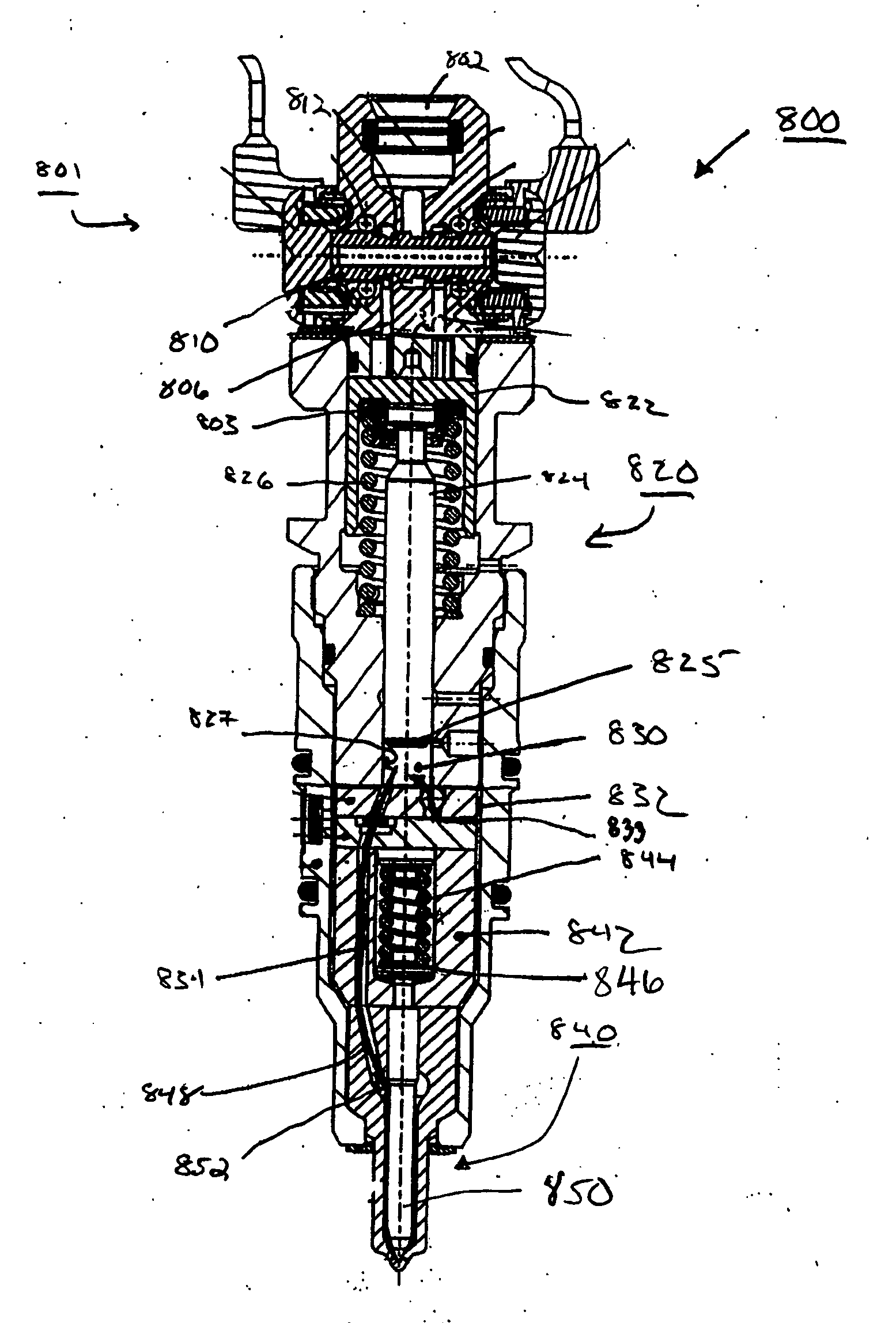
[0029] The invention is directed to an oil-activated electronically, mechanically or hydraulically controlled fuel injector, including a clevis having an optimized geometry for maintaining the performance integrity of the fuel injector. This geometry substantially prevents or eliminates scuffing of a film on a plunger, as well as metal-to-metal (or alloy) wear on the plunger and intensifier chamber. The substantial prevention or elimination of scuffing and / or wearing reduces or prevents fuel leaking and maintains performance integrity of the fuel injector. This is accomplished by allowing the plunger to “free float” within the clevis; that is, an optimized geometry of the clevis of the invention substantially eliminates side loading effects on the plunger, thereby maintaining performance integrity of the fuel injector.

Embodiments of the Oil-Activated Fuel

Injector of the Invention

[0030]FIG. 3A shows a perspective view of a clevis according to an embodiment of the invention. Referr...


PUM


Abstract

An oil activated fuel injector includes a clevis having an optimized geometry. The optimized geometry substantially eliminates side loading effects of a plunger during operation, thereby maintaining performance integrity of the fuel injector. The optimized geometry includes a profile larger than a head portion of a plunger in order to allow the plunger to free float.

Description

BACKGROUND OF THE INVENTION [0001] 1. Field of the Invention [0002] The invention generally relates to a fuel injector and to an optimized geometry of a clevis, and, more particularly, to a clevis having an optimized geometry for substantially eliminating side loading effects on a plunger during operation of the fuel injector, thereby maintaining fuel injector performance integrity. [0003] 2. Background Description [0004] There are many types of fuel injectors designed to inject fuel into a combustion chamber of an engine. For example, fuel injectors may be mechanically, electrically or hydraulically controlled in order to inject fuel into the combustion chamber of the engine. In the hydraulically actuated systems, a control valve body may be provided with two, three or four way valve systems, each having grooves or orifices which allow fluid communication between working ports, high pressure ports, and venting ports of the control valve body of the fuel injector and the inlet area....

Claims


Application Information

Patent Timeline
26 Jan 2006
Publication
US20060016915A1
IPC
F02M59/00
CPC
F02M57/025; F02M57/026; F02M59/105; F02M59/30; F02M59/44; F02M63/0063; F02M61/20; F02M63/0007
Inventors
GUMMADAVELLI, VENU; MARTIN, STEFFEN