Organic light-emitting diode and display

A technology of light-emitting diodes and organic light-emitting layers, applied in electroluminescent light sources, light sources, electric light sources, etc., can solve problems such as uneven current, worsening characteristics, and rising panel temperature.

Active Publication Date: 2006-09-06
AU OPTRONICS CORP
View PDF0 Cites 12 Cited by
  • Summary
  • Abstract
  • Description
  • Claims
  • Application Information

AI Technical Summary

Problems solved by technology

However, since the metal oxide film or semiconductor film of the intermediate layer is not a perfect conductor, its energy barrier is high so that electron or hole injection characteristi

Method used


Image

  • Organic light-emitting diode and display
  • Organic light-emitting diode and display
  • Organic light-emitting diode and display

Examples


Embodiment Construction

[0032] The "organic light-emitting diode and its display" of the present invention will be described in detail in conjunction with the icons, and the preferred embodiments will be described as follows:

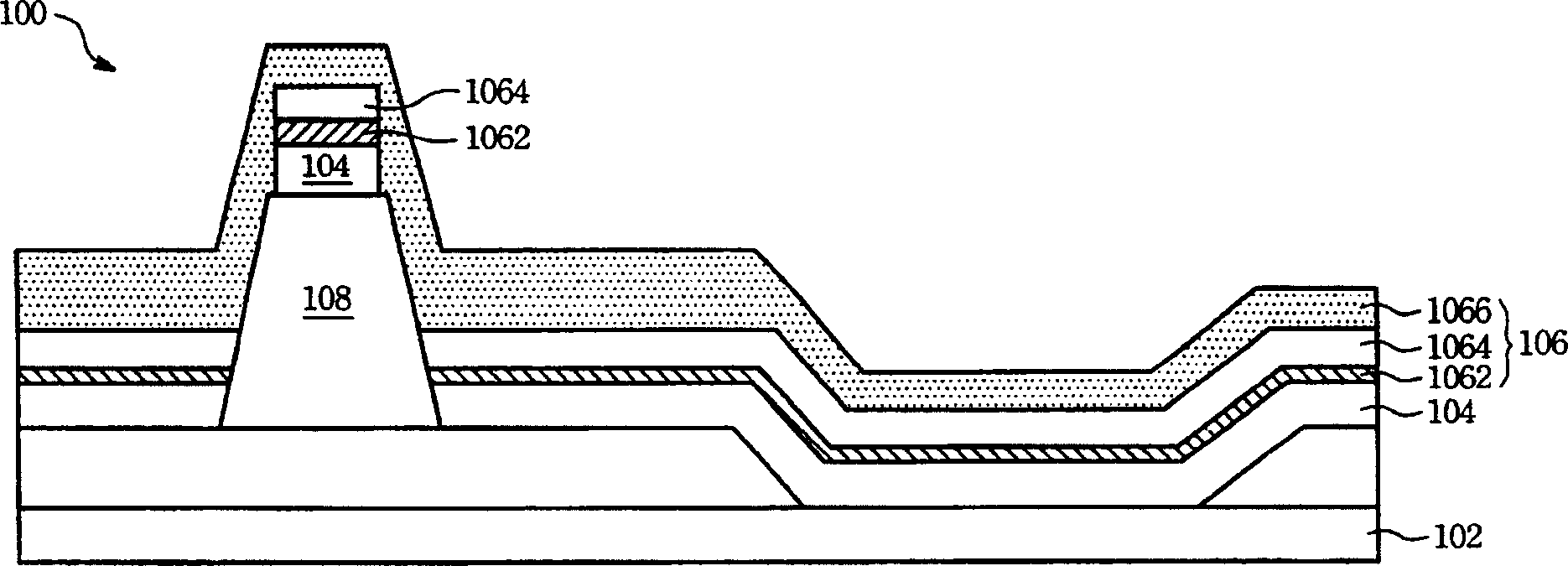
[0033] Please refer to figure 1 , is the organic light emitting diode of the present invention. The organic light emitting diode 100 includes a transparent electrode 102 , an organic light emitting layer 104 and an antireflection electrode 106 . The organic light-emitting layer 104 is located between the transparent electrode 102 and the anti-reflection electrode 106 and includes a low-molecular organic material or a high-molecular organic material.

[0034] The anti-reflection electrode 106 includes a first conductive layer 1062 , a second conductive layer 1066 and a non-metal layer 1064 . The non-metallic layer 1064 is interposed between the first conductive layer 1062 and the second conductive layer 1066 . The first conductive layer 1062 is located between the organic li...


PUM


Abstract

An organic LED includes a transparency electrode, an organic luminescent layer, an antireflection and an auxiliary electrode. Said Organic luminescent layer is located between transparency electrode and antireflection electrode, antireflection electrode including first conducting layer, a second conducting layer and a nonmetal layer, said first conducting layer located between organic luminescent layer and nonmetal layer, said nonmetal layer located between first conducting layer and second conducting layer, auxiliary electrode penetration nonmetal layer and connecting said first conducting layer to second conducting layer. Above-mentioned organic LED can be used in an organic electro photoluminescence display.

Description

technical field [0001] The invention relates to an organic light-emitting diode and its display, in particular to a low-resistance organic light-emitting diode and its display. Background technique [0002] Organic light-emitting diodes have characteristics such as low operating voltage and high luminous efficiency, so they are suitable as light-emitting elements for flat-panel displays. The basic structure of an organic light-emitting diode includes a plurality of stacked organic layers sandwiched between two electrodes. In single-sided flat-panel displays, OLEDs have a reflective electrode and a transparent electrode. The reflective electrode is generally a metal material with a low work function, and serves as a cathode for electron injection. Since part of the light generated by the OLED is reflected by the reflective electrode and guided to the transparent electrode, the reflective electrode also helps to enhance brightness. [0003] However, the ambient light enteri...

Claims


Application Information

Patent Timeline
IPC IPC(8): H01L51/50H01L51/52H01L51/56H01L27/32H01L21/82H05B33/26H05B33/10
Inventor 李世昊
Owner AU OPTRONICS CORP
Why Eureka
Try Eureka