Rugged low light reflectivity electrical contact

a low light reflectivity, electrical contact technology, applied in the direction of coupling device connection, butt, weapons, etc., can solve the problem of being susceptible to entanglement, achieve the effect of minimizing the light reflectivity of the electrical contact, high electrical conductivity, and maximizing the attenuation of reflected ligh

Active Publication Date: 2012-03-27
T WORX HLDG LLC
View PDF42 Cites 69 Cited by
  • Summary
  • Abstract
  • Description
  • Claims
  • Application Information

AI Technical Summary

Benefits of technology

[0009]Light reflectivity of the electrical contact is minimized by the use of a conductive mesh grid, which is attached to an underlying conductive surface. The conductive mesh grid (also termed “mesh grid” herein) comprises a substantially planar structure, typically a matrix of interconnected wires with apertures formed between the intersecting wires, and is used to form the outer surface of the electrical contact. The weave density, weave geometry, and wire diameter of the conductive mesh grid maximizes the attenuation of reflected light in the visible spectrum, yet maintains high electrical conductivity and a lack of sensitivity to contamination via the choice of materials used to implement the Low Reflectivity Contact.
[0010]The Low Reflectivity Contact is designed for use in an unprotected manner where the electrical contacts are exposed to harsh ambient environmental conditions. The Low Reflectivity Contact as disclosed herein is part of an overall Weapons Accessory Power System which provides the following benefits:

Problems solved by technology

The power transfer between the power source and the power-consuming accessories should be via a permanent power distribution fixture mounted on the weapon, yet susceptible to quick connect mounting and dismounting of the power-consuming accessory, and absent the use of connectors with their tethering cables, which are susceptible to entanglement.

Method used


Image

  • Rugged low light reflectivity electrical contact
  • Rugged low light reflectivity electrical contact
  • Rugged low light reflectivity electrical contact

Examples


Embodiment Construction

Definitions

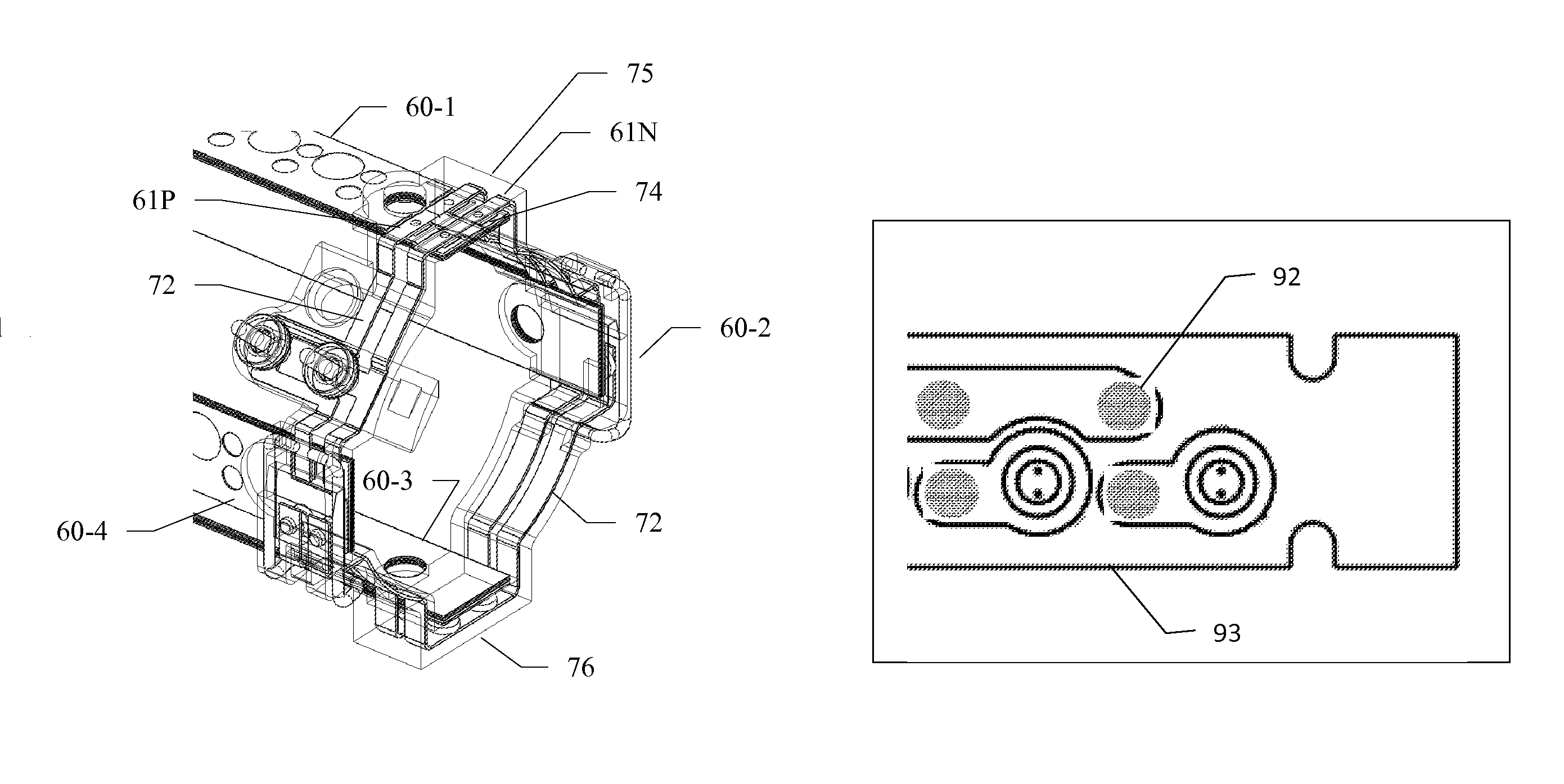
[0034]Contact—One-half of a Contact Pair consisting of an electrically conductive surface which is electrically connected to a power source or power-consuming device.

[0035]Contact Pair—A set of two Contacts which, when brought together in mechanical contact, complete an electrical circuit enabling the transfer of electrical power and / or electrical signals therebetween.

[0036]Visible Spectrum—The visible spectrum is the portion of the electromagnetic spectrum that is visible to (can be detected by) the human eye. Electromagnetic radiation in this range of wavelengths is called “visible light” or simply “light”. A typical human eye responds to wavelengths from about 390 nm to 750 nm. In terms of frequency, this corresponds to a band in the vicinity of 400 THz to 790 THz.

[0037]Electrical Resistivity—Electrical Resistivity is a measure of how strongly a material opposes the flow of electric current. A low resistivity indicates a material that readily allows the movement of ele...


PUM


Abstract

The Low Reflectivity Contact has a low coefficient of light reflection, is rugged with respect to harsh ambient environmental conditions, provides a low resistance electrical connection, and is adapted for use in quick-connect applications. Light reflectivity of the contact is minimized by the use of a conductive mesh that is used to implement the electrical contact. The weave density and wire diameter of the conductive mesh maximizes the attenuation of reflected light in the visible spectrum, yet maintains high electrical conductivity and a lack of sensitivity to contamination via the choice of materials used to implement the Low Reflectivity Contact.

Description

CROSS-REFERENCE TO RELATED APPLICATIONS[0001]This application claims the benefit of U.S. Provisional Patent Application Ser. No. 61 / 183,250 filed on Jun. 2, 2009 entitled “Non-Reflective, Conductive Mesh, Environmentally Robust Electrical Contacts.” This application is also a continuation-in-part of U.S. patent application Ser. No. 12 / 689,430 filed on Jan. 19, 2010 entitled “Rifle Accessory Rail, Communication And Power Transfer System”, which claims the benefit of U.S. Provisional Patent Application Ser. No. 61 / 145,248 filed on Jan. 16, 2009; U.S. patent application Ser. No. 12 / 689,436 filed on Jan. 19, 2010 entitled “Accessory Mount For Rifle Accessory Rail Communication And Power Transfer System, Accessory Attachment”, which claims the benefit of U.S. Provisional Patent Application Ser. No. 61 / 145,216 filed on Jan. 16, 2009; U.S. patent application Ser. No. 12 / 689,437 filed on Jan. 19, 2010 entitled “Rifle Accessory Rail Communication And Power Transfer System—Communication”, whi...

Claims


Application Information

Patent Timeline
Patent Type & Authority Patents(United States)
IPC IPC(8): F41A19/00
CPCF41C23/22F41C27/00F41G1/387F41G11/003
Inventor DODD, JAMES S.TILTON, JAYFELDMAN, BEN
Owner T WORX HLDG LLC
Why Eureka
Try Eureka