Sound reduction assembly, a ring configured to attenuate sound and a method

a technology of reducing assembly and attenuating sound, which is applied in the direction of bearing unit rigid support, gearing details, transportation and packaging, etc., can solve the problem that rotating components may produce noise during operation

Active Publication Date: 2022-07-07
GM GLOBAL TECH OPERATIONS LLC
View PDF8 Cites 2 Cited by
  • Summary
  • Abstract
  • Description
  • Claims
  • Application Information

AI Technical Summary

Problems solved by technology

These rotating components m...

Method used


Image

  • Sound reduction assembly, a ring configured to attenuate sound and a method
  • Sound reduction assembly, a ring configured to attenuate sound and a method
  • Sound reduction assembly, a ring configured to attenuate sound and a method

Examples


Embodiment Construction

[0029]Those having ordinary skill in the art will recognize that all directional references (e.g., above, below, upward, up, downward, down, top, bottom, left, right, vertical, horizontal, etc.) are used descriptively for the FIGS. to aid the reader's understanding, and do not represent limitations (for example, to the position, orientation, or use, etc.) on the scope of the disclosure, as defined by the appended claims.

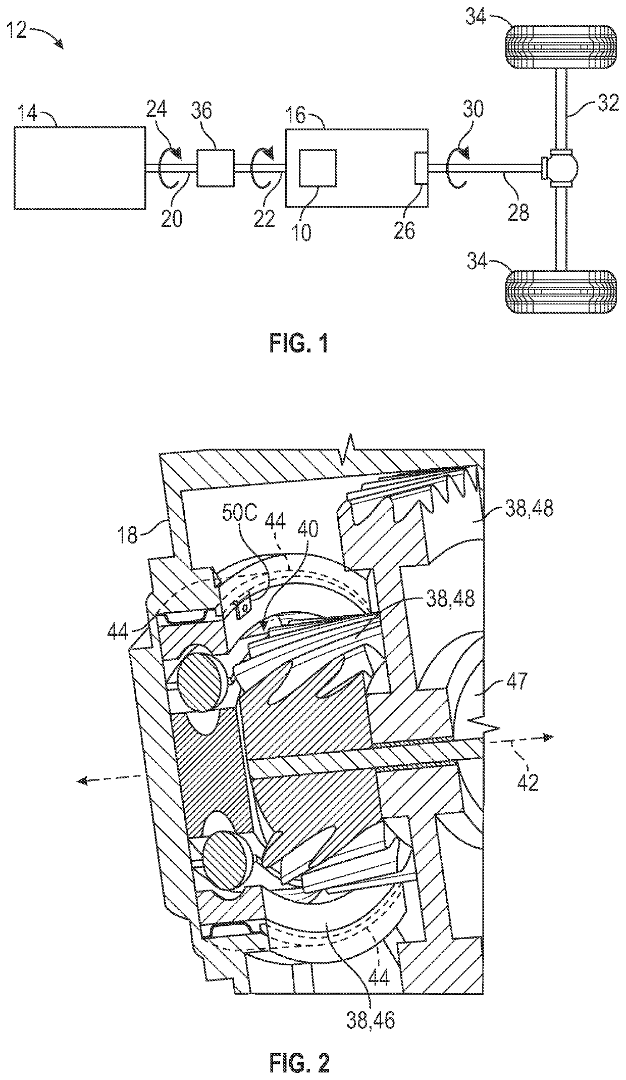
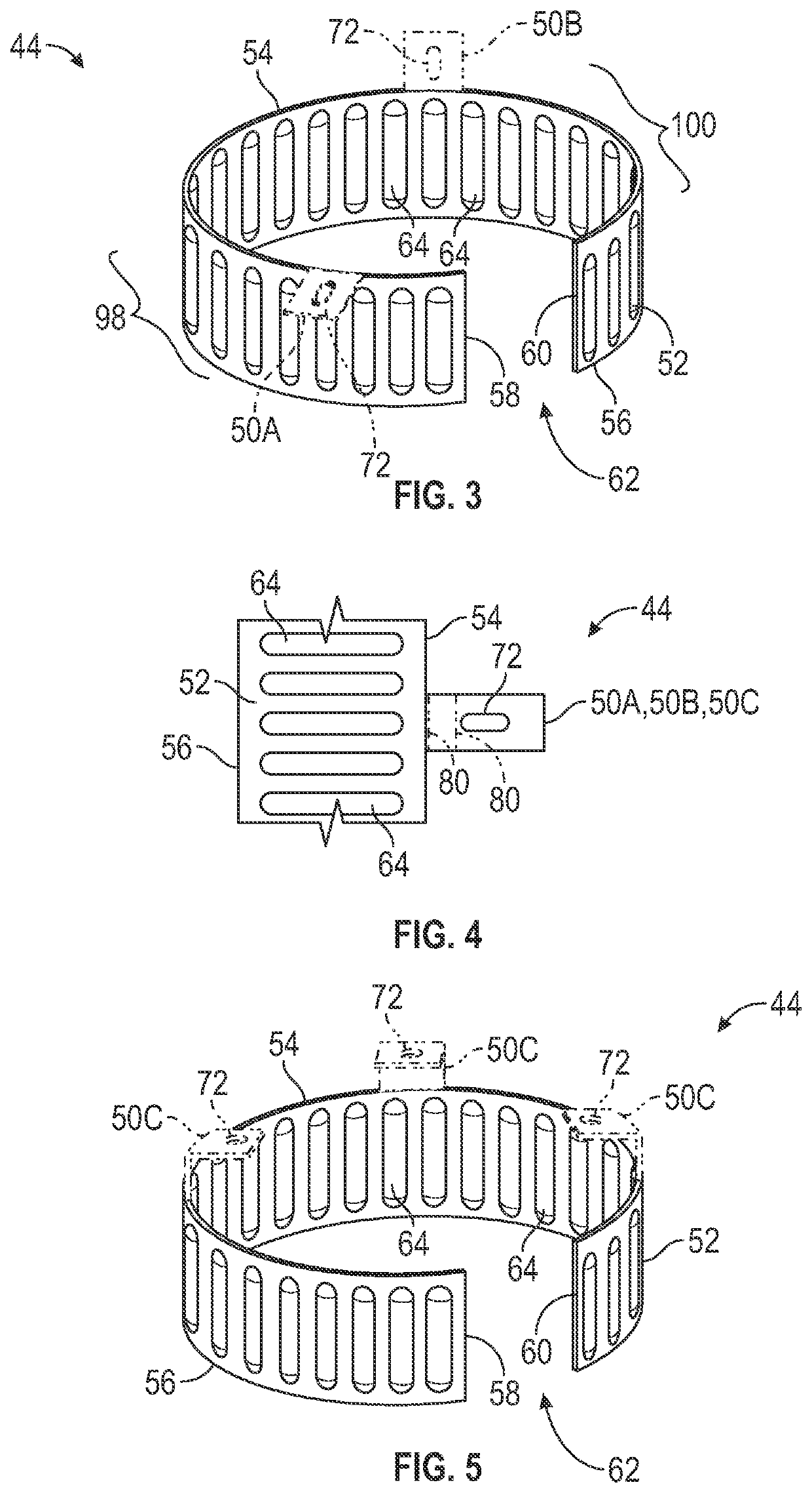
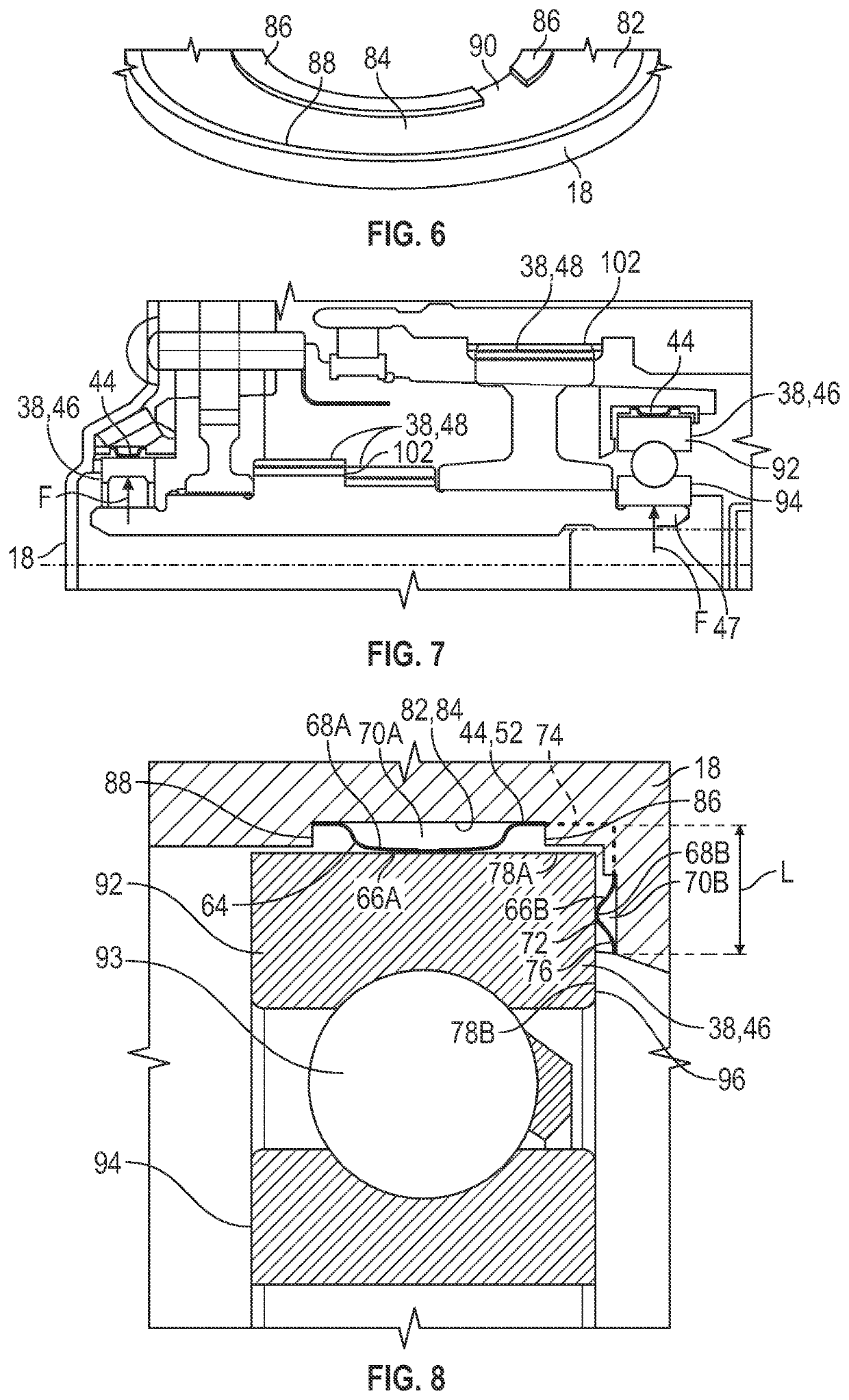
[0030]Referring to the FIGS., wherein like numerals indicate like or corresponding parts throughout the several views, a sound reduction assembly 10 is generally shown in FIG. 1 in an example implementation of the sound reduction assembly 10. Generally, the sound reduction assembly 10 may be used to attenuate sound that is produced or generated via moving parts, which will be discussed further below. That is, for example, the sound reduction assembly 10 may be used to attenuate sound inducing vibrations produced or generated via moving parts.

[0031]Specifically, as sh...


PUM


Abstract

A sound reduction assembly includes a housing and a component supported via the housing. The component is movable relative to the housing. The sound reduction assembly includes a ring coupled to the component and the housing. The ring is configured to attenuate sound inducing vibrations in response to operation of the component. The ring includes a flange fixed relative to the housing to maintain a position of the ring relative to the component which maximizes attenuation of the sound in response to operation of the component. A method of utilizing a ring to attenuate sound inducing vibrations in response to operation of a component inside of a housing. A torque is selected to be applied to the ring. A stiffness of the ring is determined based on a stiffness-torque curve utilizing the selected torque to maximize attenuation of the sound. The ring is manufactured to meet the determined stiffness.

Description

INTRODUCTION[0001]Vehicles include many components that are rotatable during operation. These rotating components may produce noise during operation. This noise may be heard by an occupant of the vehicle.SUMMARY[0002]The present disclosure provides a sound reduction assembly that includes a housing and a component supported via the housing. The component is movable relative to the housing. The sound reduction assembly also includes a ring coupled to the component and the housing. The ring is configured to attenuate sound inducing vibrations in response to operation of the component. The ring includes a flange fixed relative to the housing to maintain a position of the ring relative to the component which maximizes attenuation of the sound in response to operation of the component.[0003]In certain aspects, the ring includes a body that extends to a first distal edge and a second distal edge that oppose each other. Generally, the flange protrudes from one of the first distal edge and ...

Claims


Application Information

Patent Timeline
IPC IPC(8): F16H57/028F16H57/021
CPCF16H57/028F16H57/021B60R13/0884F16C19/527F16C35/077F16C27/04F16C19/06
Inventor ZHOU, SEN J.MILLER, JOHNFOULKES, MARTIN G.CURTIS, JEFFREY D.GAYNEY, JACK M.
Owner GM GLOBAL TECH OPERATIONS LLC
Why Eureka
Try Eureka