Noise reduction tubes

Inactive Publication Date: 2005-09-22
DANGELO JOHN P
View PDF13 Cites 28 Cited by
  • Summary
  • Abstract
  • Description
  • Claims
  • Application Information

AI Technical Summary

Benefits of technology

[0008] This invention is intended for the reduction of sound propagating through a duct. The invention allows the tuning of the acoustic treatment used to reduce the sound propagation by accounting for changes in the frequency and propagation angle of the troublesome sound waves. The invention reduces unwanted noise propagating in a duct shaped device by attenuation by diverting a portion of the acoustic energy and reintroducing it out of phase up stream. T

Problems solved by technology

Such a noise source may be due to, but not limited to, the turbofan of an aircraft engine.
This technology is very limited in that it does not reduce noise over a large frequency range, but is mainly limited to broadband noise.
Also, liners become ineffective with time because of changes in material properties due to accumulation of dirt, dust and liquids in the absorptive material.
Also, the sound reduction obtained from liners is limited since the amount of reduction is directly proportional to the amount of surface treatment.
This adds unwanted weight to the aircraft, which affects the fuel consumption of the aircraft.
Unfortunately these devices are heavy and expensive and are not durable; i.e

Method used


Image

  • Noise reduction tubes
  • Noise reduction tubes
  • Noise reduction tubes

Examples


Example

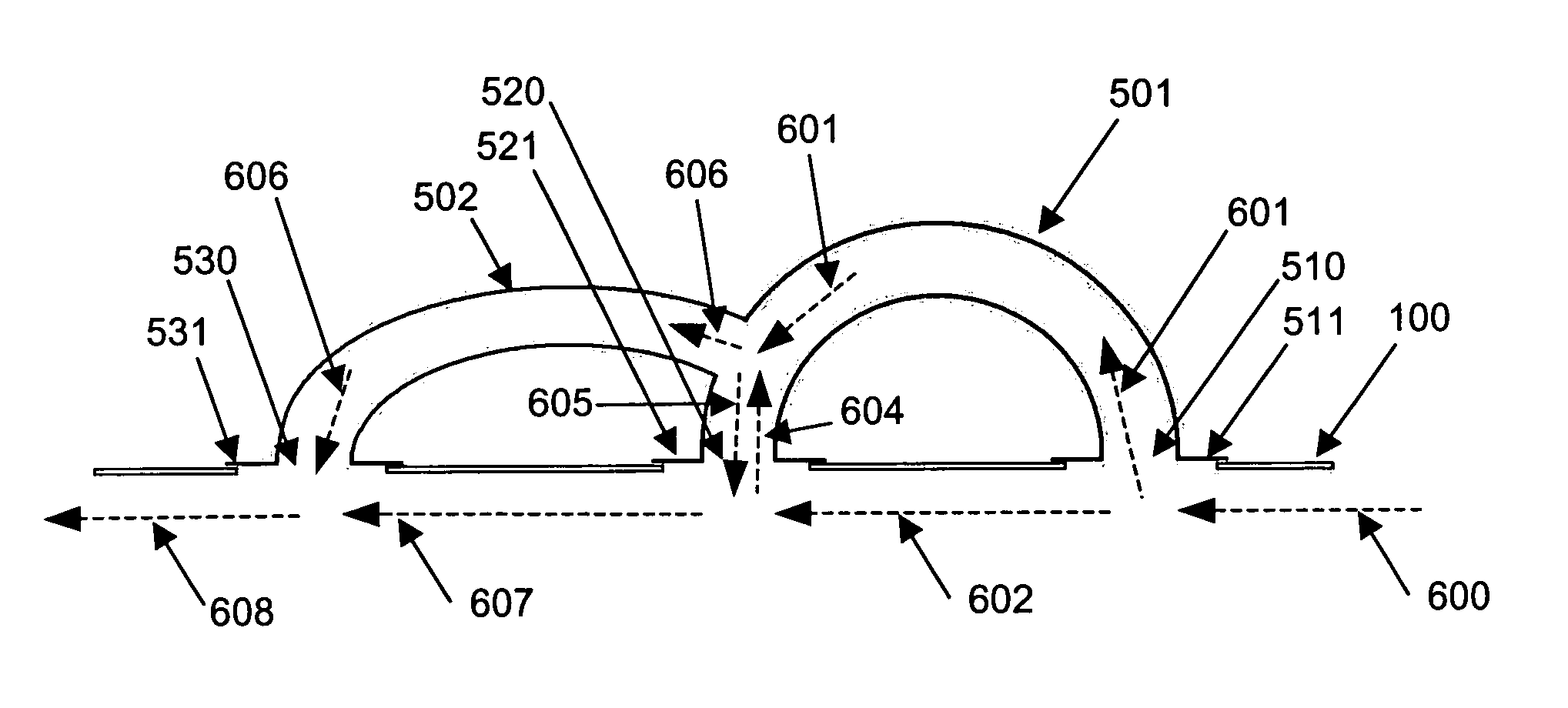
[0039] The present invention is a noise reduction system directed to reducing noise in, duct like structures, especially turbofan engines. The noise reduction system of the present invention reduces noise energy over a wide range of frequencies for both tonal and broadband components of the inlet and outlet noise for turbofan engines. The present invention utilizes at least one fixed length tube assembly comprising at least one dynamically adaptable fixed length tube as described herein, in one embodiment an array of such tubes may be arranged in a circumferential or helical array about the turbofan engine to reduce the noise levels generated. The assembly or assemblies may also be placed at the inlet, and in other locations, such as the upstream or downstream locations from the turbofan engine. The inlet and outlet of the tubes of the assembly can be placed parallel to the engine axis or at an angle. By attaching an array of dynamically adaptable fixed length tubes of appropriate l...


PUM


Abstract

The invention uses tubes for the reduction of radiated duct noise. The tubes may be used to attenuate narrow band noise by diverting a portion of the acoustic energy through the tubes back into the duct. Upon reintroducing the diverted flow out of phase with the primary flow, acoustic cancellation is achieved. The frequency at which this occurs is dependent on the difference in the path lengths through the tubes and the separation distance—the distance separating the inlet and outlet of the tube. This invention can be used over varying frequency ranges by using an arrangement of flexible, constant length tubes. The effective frequency range is tailored by varying the separation distance and also allows the varying the angular arrangement of the tubes for more effective attenuation of spinning modes having varying propagation angle.

Description

CROSS-REFERENCE TO RELATED APPLICATIONS [0001] This application claims priority to U.S. provisional patent application No. 60 / 554,269, filed Mar. 18, 2004, the contents of which are incorporated in their entirety.BACKGROUND [0002] A noise reduction system is often used to reduce noise energy in a duct or duct-like device due to some noise source. Such a noise source may be due to, but not limited to, the turbofan of an aircraft engine. Over the last several decades, much work has been done to attenuate noise generated by aircraft engines. [0003] There are currently two available alternative technologies for reducing inlet noise in jet engines. One technology simply employs “liners” on the engine compartment which are internal coatings that absorb acoustic energy at the engine inlet. This technology is very limited in that it does not reduce noise over a large frequency range, but is mainly limited to broadband noise. Also, liners become ineffective with time because of changes in ma...

Claims


Application Information

Patent Timeline
IPC IPC(8): F01N1/00F01N1/16F01N13/18F02C7/045F02K1/08F02K3/06F02M35/00F02M35/12
CPCF01N1/00F01N2470/04F02C7/045F02K1/08F05D2260/962Y02T50/671F02M35/1227F05D2260/96F02K3/06Y02T50/60
Inventor D'ANGELO, JOHN P.
Owner DANGELO JOHN P
Why Eureka
Try Eureka