Clamped cascode level shifter circuit

a level shifter and cascode technology, applied in the direction of logic circuit coupling/interface arrangement, power consumption reduction, pulse technique, etc., can solve the problems of increasing manufacturing cost, aggravated toggling of these devices from one state to another, and preventing continuous current conduction, hysteretic switching

Inactive Publication Date: 2001-03-13
AME
View PDF4 Cites 87 Cited by
  • Summary
  • Abstract
  • Description
  • Claims
  • Application Information

AI Technical Summary

Benefits of technology

An improved level shifter circuit is provided by toggling a "flying Flip-Flop" comprising a cross-coupled inverter pair with control devices driven out of phase through a pair of cascode transistors. The cross-coupled inverter pa...

Problems solved by technology

A major disadvantage of level shifter circuit 10 is that devices N1, N2, P1 and P2 are all vulnerable to the full voltage excursion from ground to Vboost.
This requires special high voltage processing to minimize or avoid the potential of d...

Method used


Image

  • Clamped cascode level shifter circuit
  • Clamped cascode level shifter circuit
  • Clamped cascode level shifter circuit

Examples


Embodiment Construction

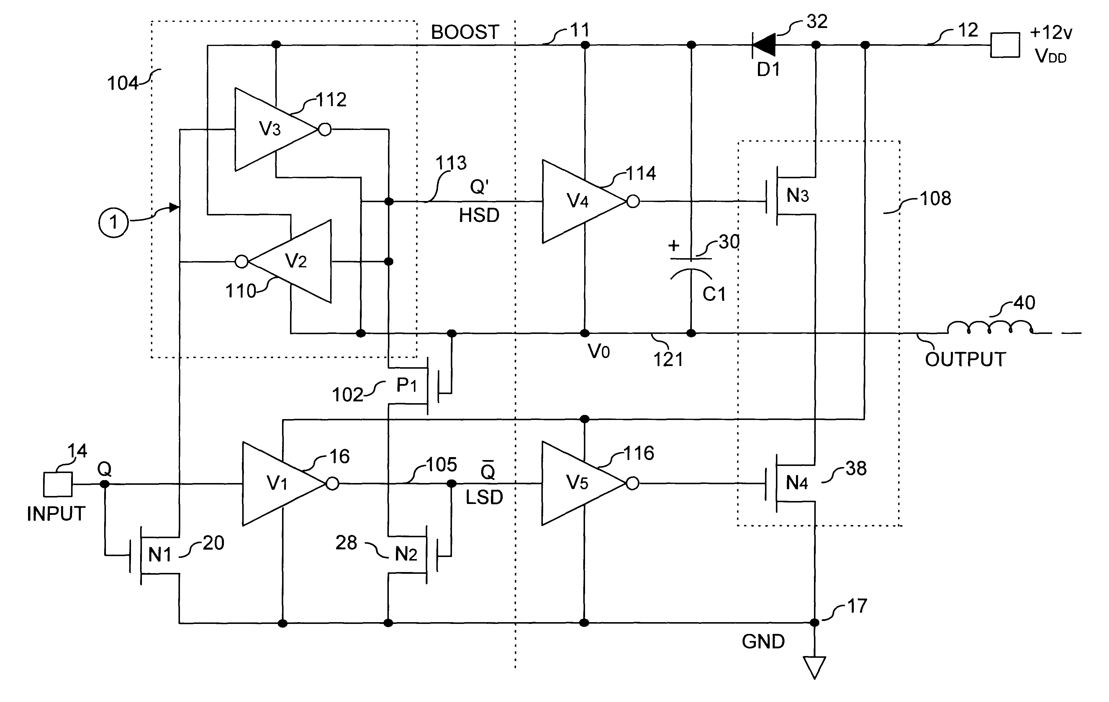
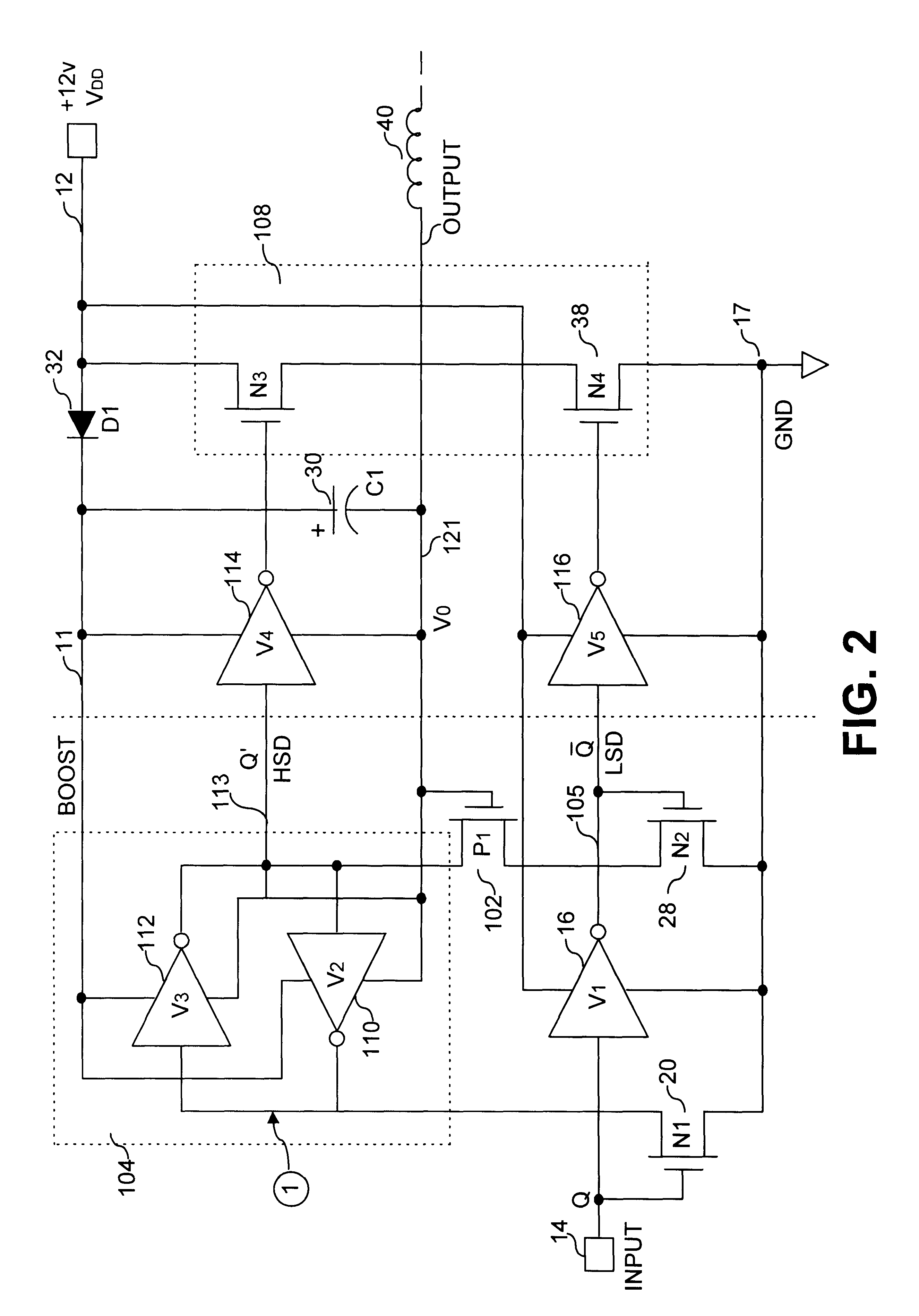
FIG. 2 illustrates a clamped cascode level shifter in accordance with the principles of this invention. Level shifter circuit 100 comprises a first inverter (V1) 16, a pair of control devices 20 and 28 (N1 and N2, respectively), and a first cascode clamp 102 (P1). In the preferred embodiment, a second cascode clamp (P2), not shown, is also provided for circuit symmetry and improved switching speed and performance (i.e., as shown in FIG. 3). A "flying Flip-Flop" 104 is provided comprising two back to back inverters 110 and 112 (V2 and V3, respectively) with ground return of each inverter coupled to an output of a half bridge circuit comprising switching devices 34 and 38 (N3 and N4, respectively).

As illustrated in FIG. 2, the source of device P1 is coupled at a voltage equivalent to a gate voltage above ground (i.e., Vg), thus allowing toggling of output node Q' 113 of inverter pair V2 and V3 between a voltage source rail voltage 12, (i.e., Vboost, wherein Vboost=VDD-VD1) and ground,...


PUM


Abstract

An improved level shifter circuit that toggles a "flying Flip-Flop" comprising a cross-coupled inverter pair with control devices driven out of phase through a pair of cascode transistors. The cross-coupled inverter pair provides pull-up to the positive rail, clamping to a High Side-Common (HSC), and providing Hysteretic Switching. The cascode transistors restrict the pull-down of the control devices, thereby preventing continuous current conduction.

Description

This invention relates to the field of circuit designs, particularly to voltage level shifter circuits.BACKGROUND OF INVENTIONLevel shifter circuits are frequently used to translate one voltage level to another. For example, to conserve power, the "core" voltage within an IC frequently operates at low voltage, but is scaled up at the output. A special class of level shifters is the "half bridge drivers" in which complementary signals are applied to an "upper" and "lower" device. In this application, typically the lower device does not require any special signal processing. The upper device requires level shifting in order to provide adequate Gate-Source enhancement, which is necessary because the source potential is not referenced to ground.FIG. 1 illustrates a typical half-bridge circuit with a level shifter. Level shifter circuit 10 comprises a first inverter (V1) 16, a pair of control devices 20 and 28 (N1 and N2, respectively), and a cross-coupled pair devices 18 and 24 (P1 and ...

Claims


Application Information

Patent Timeline
IPC IPC(8): H03K19/00H03K19/017H03K19/003H03K19/01H03K19/0185
CPCH03K19/0013H03K19/00315H03K19/01714H03K19/018521
Inventor ROSENTHAL, BRUCE
Owner AME
Why Eureka
Try Eureka