Mutual coupling method for calibrating a phased array

a phased array and phased array technology, applied in the field of radar systems, can solve the problems of prior art phased array calibration techniques using calibrated internally generated and distributed test signals, add cost, weight and complexity to the system, and the scanning process for initial calibration can be very time-consuming

Inactive Publication Date: 2006-06-08
LOCKHEED MARTIN CORP
View PDF4 Cites 85 Cited by
  • Summary
  • Abstract
  • Description
  • Claims
  • Application Information

AI Technical Summary

Benefits of technology

[0007] A method for calibrating a phase array antenna comprises performing initial measurements of array antenna elements to ensure that calibration measurements are within the linear dynamic range of receive elements contained within the array. The method includes deriving calibration coefficients from a direct measurement of a forced out of phase condition and detection of deep nulls through adjustment of amplitude and phase settings over a range of frequencies of interest.
[0008] In one configuration, a method of calibrating at least one element in a phased array antenna comprises determining a radiated energy level associated with a given transmit element in the array; determining a linear dynamic range and signal to noise ratio (SNR) for a receive element in the array for making phase and amplitude measurements within a given accuracy range; and determining a mutual coupling associated with elements in the array based on the determined signal to noise ratio and linearity parameters. For a given element within the array, other elements having a mutual coupling with the given element within the array are identified in accordance with the linear dynamic range and the SNR, to define a calibration region. The method further includes determining a first element within the other identified elements; determining a second element within the calibration region for the first element; and determining a third element within the calibration region for the second element and symmetrically opposite that of the first element relative to the second element. An RF signal is transmitted from the second element while receiving from the first and third elements initial phase and amplitude bit data. The method includes adjusting the phase bit data of the first element until a signal strength null signal is detected, where the adjusted phase bit data corresponds to a relative phase value associated with the first element relative to the third element; and adjusting the amplitude bit data of the first element until a signal strength null associated with the first element is detected, where the adjusted amplitude bit data corresponds to a relative gain value associated with the first element relative to the third element. The calibration coefficients of the phased array are determined based on the relative gain and phase values.

Problems solved by technology

In general the near-field and far-field scanning process for initial calibration can be very time consuming, especially for arrays with large numbers of elements.
Prior art phased array calibration techniques using a calibrated internally generated and distributed test signal add cost, weight and complexity to the system.
Other calibration techniques have used external probes which require external hardware, add cost, weight and complexity to the system and can be subject to multipath reflections and external interference.
They may also be unsuitable for tactical equipment.
However, the prior art includes a number of drawbacks and limitations associated with the present mutual coupling calibration implementations.
However, full power transmit signals may not be within the linear dynamic range of near neighboring receive elements, resulting in distorted or ineffective array calibration over a wide band of signal energy levels.
In addition, the prior art solutions include accuracy limitations in that neighboring elements may have very closely matching gain and phase values, while the array calibration measurements may be required to resolve intensity differences of fractions of a decibel (dB) or less and phase differences of only a few degrees.

Method used


Image

  • Mutual coupling method for calibrating a phased array
  • Mutual coupling method for calibrating a phased array
  • Mutual coupling method for calibrating a phased array

Examples


Embodiment Construction

[0022] It is to be understood that the figures and descriptions of the present invention have been simplified to illustrate elements that are relevant for a clear understanding, while eliminating, for the purpose of clarity, many other elements found in radar systems and methods of making and using the same. Those of ordinary skill in the art may recognize that other elements and / or steps may be desirable in implementing the present invention. However, because such elements and steps are well known in the art, and because they do not facilitate a better understanding of the present invention, a discussion of such elements and steps is not provided herein.

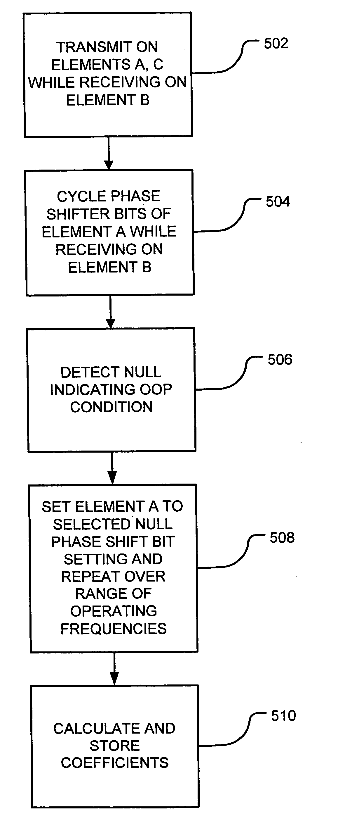
[0023] According to an aspect of the invention, a method for calibrating a phase array antenna comprises performing initial measurements of array antenna elements to ensure that calibration measurements are within the linear dynamic range of receive elements contained within the array. Calibration coefficients are derived from a di...


PUM


Abstract

A method for calibrating a phase array antenna comprises performing initial measurements of array antenna elements to ensure that calibration measurements are within the linear dynamic range of receive elements contained within the array. The method includes deriving calibration coefficients from a direct measurement of a forced out of phase condition and detection of deep nulls through adjustment of amplitude and phase settings over a range of frequencies of interest.

Description

FIELD OF INVENTION [0001] The present invention relates generally to radar systems and more specifically to a system and method for calibrating phased array antennas. BACKGROUND [0002] Phased array antenna systems employ a plurality of individual antennas or subarrays of antennas that are separately excited to cumulatively produce a transmitted electromagnetic wave that is highly directional. The radiated energy from each of the individual antenna elements or subarrays is of a different phase, respectively, so that an equiphase beam front or cumulative wave front of electromagnetic energy radiating from all of the antenna elements in the array, travels in a selected direction. The differences in phase or timing among the antenna activating signals determines the direction in which the cumulative beam from all of the individual antenna elements is transmitted. Analysis of the phases of return beams of electromagnetic energy detected by the individual antennas in the array similarly a...

Claims


Application Information

Patent Timeline
Patent Type & Authority Applications(United States)
IPC IPC(8): H01Q3/26H04B17/00
CPCH01Q3/267
Inventor COLLINSON, DONALD L.
Owner LOCKHEED MARTIN CORP
Why Eureka
Try Eureka